Information injection-pump assembly
BOSCH
9 400 612 293
9400612293
ZEXEL
101400-9031
1014009031
YANMAR
12995351011
12995351011
Rating:
Service parts 101400-9031 INJECTION-PUMP ASSEMBLY:
1.
_
4.
SUPPLY PUMP
5.
AUTOM. ADVANCE MECHANIS
6.
COUPLING PLATE
7.
COUPLING PLATE
8.
_
9.
_
10.
NOZZLE AND HOLDER ASSY
11.
Nozzle and Holder
12.
Open Pre:MPa(Kqf/cm2)
13.
NOZZLE-HOLDER
14.
NOZZLE
15.
NOZZLE SET
Cross reference number
BOSCH
9 400 612 293
9400612293
ZEXEL
101400-9031
1014009031
YANMAR
12995351011
12995351011
Zexel num
Bosch num
Firm num
Name
9 400 612 293
12995351011 YANMAR
INJECTION-PUMP ASSEMBLY
4TNE98 * K 14BC PE4A,5A, PE
4TNE98 * K 14BC PE4A,5A, PE
Calibration Data:
Adjustment conditions
Test oil
1404 Test oil ISO4113 or {SAEJ967d}
1404 Test oil ISO4113 or {SAEJ967d}
Test oil temperature
degC
40
40
45
Nozzle and nozzle holder
105780-8140
Bosch type code
EF8511/9A
Nozzle
105780-0000
Bosch type code
DN12SD12T
Nozzle holder
105780-2080
Bosch type code
EF8511/9
Opening pressure
MPa
17.2
Opening pressure
kgf/cm2
175
Injection pipe
Outer diameter - inner diameter - length (mm) mm 6-2-600
Outer diameter - inner diameter - length (mm) mm 6-2-600
Overflow valve
131424-1520
Overflow valve opening pressure
kPa
157
123
191
Overflow valve opening pressure
kgf/cm2
1.6
1.25
1.95
Tester oil delivery pressure
kPa
157
157
157
Tester oil delivery pressure
kgf/cm2
1.6
1.6
1.6
Direction of rotation (viewed from drive side)
Right R
Right R
Injection timing adjustment
Direction of rotation (viewed from drive side)
Right R
Right R
Injection order
1-3-4-2
Pre-stroke
mm
3.6
3.55
3.65
Beginning of injection position
Drive side NO.1
Drive side NO.1
Difference between angles 1
Cal 1-3 deg. 90 89.5 90.5
Cal 1-3 deg. 90 89.5 90.5
Difference between angles 2
Cal 1-4 deg. 180 179.5 180.5
Cal 1-4 deg. 180 179.5 180.5
Difference between angles 3
Cyl.1-2 deg. 270 269.5 270.5
Cyl.1-2 deg. 270 269.5 270.5
Injection quantity adjustment
Adjusting point
A
Rack position
9.3
Pump speed
r/min
1000
1000
1000
Average injection quantity
mm3/st.
59
58
60
Max. variation between cylinders
%
0
-2.5
2.5
Basic
*
Fixing the lever
*
Injection quantity adjustment_02
Adjusting point
C
Rack position
6.3+-0.5
Pump speed
r/min
525
525
525
Average injection quantity
mm3/st.
10.5
9.5
11.5
Max. variation between cylinders
%
0
-15
15
Fixing the rack
*
Injection quantity adjustment_03
Adjusting point
D
Rack position
10.1++
Pump speed
r/min
100
100
100
Average injection quantity
mm3/st.
80
75
85
Fixing the lever
*
Rack limit
*
Test data Ex:
Governor adjustment
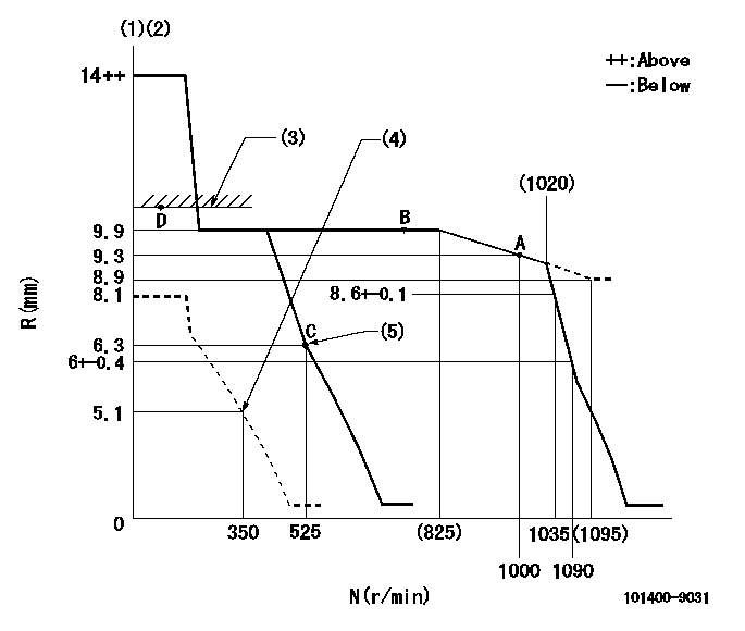
N:Pump speed
R:Rack position (mm)
(1)Target notch: K
(2)Tolerance for racks not indicated: +-0.05mm.
(3)RACK LIMIT
(4)Set idle sub-spring
(5)Main spring setting
----------
K=10
----------
----------
K=10
----------
Speed control lever angle

F:Full speed
I:Idle
(1)Stopper bolt setting
----------
----------
a=5deg+-5deg b=16deg+-5deg
----------
----------
a=5deg+-5deg b=16deg+-5deg
Stop lever angle
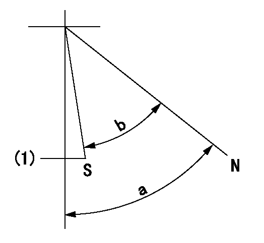
N:Pump normal
S:Stop the pump.
(1)Normal stop
----------
----------
a=58deg+-5deg b=53deg+-5deg
----------
----------
a=58deg+-5deg b=53deg+-5deg
Timing setting

(1)Pump vertical direction
(2)Position of camshaft's key groove at No 1 cylinder's beginning of injection
(3)-
(4)-
----------
----------
a=(60deg)
----------
----------
a=(60deg)
Information:
6. Full-load Quantity for Starting a warmed-up Engine
When the engine is warmed-up, it is not necessary to operate the lever (9) for additional fuel.7. Stopping the Engine
For stopping the engine, the starting and stopping lever (9) must be pulled beyond the starting position until it rests firmly against the stop. When pulling the lever slowly, the engine will speed up again before stopping.8. Operating the Tractor
The hydraulic governor of the distributor-type pump functions in the same manner as a mechanical governor (RSV governor) of an in-line pump. It is, however, more sensitive to response than the mechanical governor.Pump Illustrations
Fuel Circuit Of Distributor - Type Pump
Checking The Fuel-Injection Pump Drive And Replacing Components (as from 3 cylinder engine)
1. Check the gearwheel and hub or injection timer. If necessary, dismantle the gearwheel from the hub or from the injection timer.2. Renew the defective component.
7-492.1 Assemble the gearwheel and hub so that the punch mark registers with the groove in the hub.Fig. 7-49, right2.2 Assemble the gearwhell to the injection timer so that the recess in the former registers with the groove in the hub.Fig. 7-49, left Important:As from 1975, the hub was modified in the case of rigid drive.
7-502.3 In the case of in-line injection pump, mount gearwheel onto steel hub.Fig. 7-50, right2.4 In the case of distributor injection pump, mount gearwheel reversed onto the hub.Fig. 7-50 left Observe markings and angular degrees.Dismantling And Installing Injectors
Dismantling:
1. Dismantle leak-off line to injector. Disconnect injection delivery line on injection.2. Dismantle stirrup and remove thrust piece.
7-513. Remove injector using extracting device No. 150800.Fig. 7-51, Attention:In addition, use threaded piece No. 110050 in case of lateral connection of injection delivery line.Fig. 7-51, leftUse extractor No. 110030 in case of top connection of injection delivery line.Fig. 7-51, right
7-52On FL 912 W remove injector by special wrench No. 110010 plus insert No. 110020.Fig. 7-52
7-534. Remove joint washer from injector or from cylinder head, as the case may be. (Extractor No. 120630)Fig. 7-53, leftIn case of FL 912 W, remove heat insulating plate (using, for example, bent wire).Fig. 7-53, rightInstalling:
7-541. Stick new joint washer with grease (graphited side facing towards injector).Fig. 7-54 On FL 912 install heat guard as shown.Fig. 7-53, right2. Install injector.
7-553. Install thrust piece and place stirrup in position.Fig. 7-55, left4. Place washer with convex side facing stirrup and screw on nut.(See Specification Data)5. On FL 912 W align injector to injection pipe.Fig. 7-55, right
7-566. Tighten injector by special wrench No. 110010 plus insert No. 110020.Fig. 7-567. Tighten injector and fit leak-oil line with new sealing rings.Removing And Refitting Injector On Engine Provided With Exhaust Air Heating
Preliminary work:
Injector is removed.1. Stick by means of grease sealing ring to injector and insert the latter in the cylinder head.
7-572. Slip rubber seal on injector and the vertical pin (see arrow) for fixture.Fig. 7-57
7-583. Apply leak oil pan (arrow). Slip spring and spacer sleeve on pin for fixture.Fig. 7-584. Apply clamping piece and fixture.5. Apply washer the curved side of which must show towards fixture; screw on