Information injection-pump assembly
ZEXEL
101400-9030
1014009030
YANMAR
12995351010
12995351010

Rating:
Cross reference number
ZEXEL
101400-9030
1014009030
YANMAR
12995351010
12995351010
Zexel num
Bosch num
Firm num
Name
Calibration Data:
Adjustment conditions
Test oil
1404 Test oil ISO4113 or {SAEJ967d}
1404 Test oil ISO4113 or {SAEJ967d}
Test oil temperature
degC
40
40
45
Nozzle and nozzle holder
105780-8140
Bosch type code
EF8511/9A
Nozzle
105780-0000
Bosch type code
DN12SD12T
Nozzle holder
105780-2080
Bosch type code
EF8511/9
Opening pressure
MPa
17.2
Opening pressure
kgf/cm2
175
Injection pipe
Outer diameter - inner diameter - length (mm) mm 6-2-600
Outer diameter - inner diameter - length (mm) mm 6-2-600
Overflow valve
131424-1520
Overflow valve opening pressure
kPa
157
123
191
Overflow valve opening pressure
kgf/cm2
1.6
1.25
1.95
Tester oil delivery pressure
kPa
157
157
157
Tester oil delivery pressure
kgf/cm2
1.6
1.6
1.6
Direction of rotation (viewed from drive side)
Right R
Right R
Injection timing adjustment
Direction of rotation (viewed from drive side)
Right R
Right R
Injection order
1-3-4-2
Pre-stroke
mm
3.6
3.55
3.65
Beginning of injection position
Drive side NO.1
Drive side NO.1
Difference between angles 1
Cal 1-3 deg. 90 89.5 90.5
Cal 1-3 deg. 90 89.5 90.5
Difference between angles 2
Cal 1-4 deg. 180 179.5 180.5
Cal 1-4 deg. 180 179.5 180.5
Difference between angles 3
Cyl.1-2 deg. 270 269.5 270.5
Cyl.1-2 deg. 270 269.5 270.5
Injection quantity adjustment
Adjusting point
A
Rack position
9.4
Pump speed
r/min
1000
1000
1000
Average injection quantity
mm3/st.
59
58
60
Max. variation between cylinders
%
0
-2.5
2.5
Basic
*
Fixing the lever
*
Injection quantity adjustment_02
Adjusting point
C
Rack position
6.3+-0.5
Pump speed
r/min
525
525
525
Average injection quantity
mm3/st.
9
8
10
Max. variation between cylinders
%
0
-15
15
Fixing the rack
*
Injection quantity adjustment_03
Adjusting point
D
Rack position
10.3++
Pump speed
r/min
100
100
100
Average injection quantity
mm3/st.
75
70
80
Fixing the lever
*
Rack limit
*
Test data Ex:
Governor adjustment
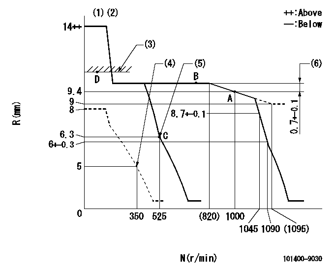
N:Pump speed
R:Rack position (mm)
(1)Target notch: K
(2)Tolerance for racks not indicated: +-0.05mm.
(3)RACK LIMIT
(4)Set idle sub-spring
(5)Main spring setting
(6)Rack difference between N = N1 and N = N2
----------
K=12 N1=1000r/min N2=700r/min
----------
----------
K=12 N1=1000r/min N2=700r/min
----------
Speed control lever angle

F:Full speed
I:Idle
(1)Stopper bolt setting
----------
----------
a=7deg+-5deg b=18deg+-5deg
----------
----------
a=7deg+-5deg b=18deg+-5deg
Stop lever angle
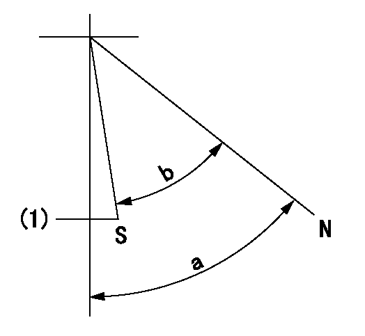
N:Pump normal
S:Stop the pump.
(1)Normal stop
----------
----------
a=58deg+-5deg b=53deg+-5deg
----------
----------
a=58deg+-5deg b=53deg+-5deg
Timing setting

(1)Pump vertical direction
(2)Position of camshaft's key groove at No 1 cylinder's beginning of injection
(3)-
(4)-
----------
----------
a=(60deg)
----------
----------
a=(60deg)
Information:
Removing And Fitting A Starter Gear Ring
It is assumed that the flywheel is dismantled.Removing:
6-1Cut through the starter gear ring with a hard chisel and remove.Fig. 6-1Refitting:
1. Heat the starter gear ring to a temperature of 120 deg. C. Place the starter gear ring with the bevelled side of the teeth facing away from flywheel.
6-22. Locate the starter gear ring on the flywheel and tap it into position so that it seats against the shoulder.Fig. 6-2Removing And Fitting A Radial Sealing Ring On The Flywheel Side
It is assumed that the flywheel has been dismantled. Removing:
6-3Apply puller No. 142700 and draw off radial sealing ring.Fig. 6-3Refitting:
6-41. Mount guide-piece of device onto crankshaft.Fig. 6-4
6-52. Lightly grease the sealing lip of the new radial seal. Place seal on guide-piece with lip facing towards crankcase and press in with device No. 142530.Fig. 6-5 Inspect crankshaft in the zone of radial seal contact. If a friction groove has been formed by the radial seal, displace the complete cover by adding gaskets accordingly.Dismantling, Installing And Sealing The Cover On The Flywheel Side (As from 3-cylinder engine)
The flywheel has already been removed.Dismantling:
1. Remove the bolts in the oil sump securing the cover on the flywheel side and the bolts securing the cover to the crankcase. Remove cover and gasket. Renew radial sealing ring. Inspect crankshaft in the zone of radial seal contact. If a friction groove has been formed by the radial seal, displace the latter in the cover.Installing:
6-112. Adhere new gasket to crankcase. Trim off the portion of gasket projecting beyond the joint surface of the sump. Fig. 6-113. Apply coat of Deutz DW 48 jointing compound to the oil sump gasket in the region of the cover.
6-124. Press new radial seal into the rear cover so that the outside surface is flush (arrow).Fig. 6-12 Prior to fitting, heat cover "hand-warm" and coat radial seal with jointing compound.
6-135. Place cover in position. Lightly pretighten cover bolts in crankcase. Fully tighten sump bolts in cover, then fully tighten bolts in crankcase.Fig. 6-13Exploded Views