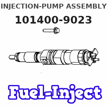
Information injection-pump assembly
BOSCH
9 400 613 221
9400613221
ZEXEL
101400-9023
1014009023
YANMAR
12995551021
12995551021

Rating:
Service parts 101400-9023 INJECTION-PUMP ASSEMBLY:
1.
_
4.
SUPPLY PUMP
5.
AUTOM. ADVANCE MECHANIS
6.
COUPLING PLATE
7.
COUPLING PLATE
8.
_
9.
_
10.
NOZZLE AND HOLDER ASSY
11.
Nozzle and Holder
12.
Open Pre:MPa(Kqf/cm2)
13.
NOZZLE-HOLDER
14.
NOZZLE
15.
NOZZLE SET
Cross reference number
Zexel num
Bosch num
Firm num
Name
101400-9023
9 400 613 221
12995551021 YANMAR
INJECTION-PUMP ASSEMBLY
4TNE98 K 14BC INJECTION PUMP ASSY PE4A,5A, PE
4TNE98 K 14BC INJECTION PUMP ASSY PE4A,5A, PE
Information:
5-9 When moving radial seal, observe correct depth of installation (pressed in). Depth 1 see Fig. 5-9, outside flush with front-end cover.
5-10Depth 2 (after shifting in front-end cover to be flush inside) : max. 1.0 mm.Fig. 5-10Dismantling And Installing The Vee-Belt Tensioner (As from 3 cylinder engine)
Dismantling:
1. Dismantle the holder for the warning system operator. Remove the vee belt driving the cooling air blower.2. Dismantle the vee-belt tensioner. Remove the rubber O-seal on the vee-belt tensioner.Installing:
5-111. Fit a new rubber O-seal on the vee-belt tensioner.Fig. 5-11
5-122. Mount the vee-belt tensioner with the idler pulley facing outwards.Fig. 5-12
5-133. Mount the holder of the warning system operator if the engine is equipped with an alarm system for breakage of the blower belt. Fit a spacer sleeve between the holder and front cover.Fig. 5-13
5-144. Check the alignment of the vee belt running from the idler pulley to the belt pulley mounted on the crankshaft.Fig. 5-145. If misalignment has to be corrected dismantle the vee-belt idler pulley.Checking And Repairing The Vee-Belt Tensioner
Tensioner is removed.
5-151. If the idler is damaged or its bearing worn, dismantle it from the tensioning lever. Check the radial clearance of the shaft of the vee-belt tensioner.Fig. 5-152. If the shaft has too much radial clearance or if the torsion spring is weak or broken, dismantle the vee-belt tensioner.
5-163. After prising out the shaft seal, press out the bearing bushings that are to be renewed. Press in new bearing bushing flush on the inside. Before pressing in the outer bearing bushing, measure the height of the shaft seal and then press in the bearing bushing deeper by this amount.Fig. 5-164. Press in shaft seal flush on outside.
5-175. Renew worn shaft. Drive the heavy-duty clamping sleeve into the large bore so that one end projects 15 mm.Fig. 5-17
5-186. To install, insert the end of the shaft at the inside. Press the end of the torsion spring into the clamping sleeve and push in the shaft completely.Fig. 5-18 If the ends of the torsion spring are of different length, insert the longer one in the clamping sleeve.7. Fit two new gaskets in the groove between the housing and shaft.
5-198. Press the tensioning lever on the shaft so that their holes are in register, with the tensioning lever pointing to the right and the long end of the clamping sleeve pointing downwards (as viewed from inside).Fig. 5-19
5-209. Assemble the idler with the old shims to the tensioning lever.Fig. 5-20Reassembling The Vee-Belt Tensioner (New Design)
Bearing bushing and shaft seal are already fitted.
5-211. Insert long end of torsion spring into shaft and place spacer washer (arrow) in position.Fig. 5-21
5-222. Insert shaft with torsion spring and spacer washer into housing. Position for short end of torsion spring - see arrow.Fig. 5-22
5-233. Push the tensioning lever onto the shaft so that the bores of shaft and lever coincide and the long end of the spring points downwards. Insert locking pin.Fig. 5-23
5-244. Assemble the idler pulley with the old shims to the tensioning lever.Fig. 5-24Dismantling And Installing
Have questions with 101400-9023?
Group cross 101400-9023 ZEXEL
Yanmar
Yanmar
101400-9023
9 400 613 221
12995551021
INJECTION-PUMP ASSEMBLY
4TNE98
4TNE98