Information injection-pump assembly
BOSCH
9 400 612 483
9400612483
ZEXEL
101400-9022
1014009022
YANMAR
12995551020
12995551020
Rating:
Service parts 101400-9022 INJECTION-PUMP ASSEMBLY:
1.
_
4.
SUPPLY PUMP
5.
AUTOM. ADVANCE MECHANIS
6.
COUPLING PLATE
7.
COUPLING PLATE
8.
_
9.
_
10.
NOZZLE AND HOLDER ASSY
11.
Nozzle and Holder
12.
Open Pre:MPa(Kqf/cm2)
13.
NOZZLE-HOLDER
14.
NOZZLE
15.
NOZZLE SET
Cross reference number
BOSCH
9 400 612 483
9400612483
ZEXEL
101400-9022
1014009022
YANMAR
12995551020
12995551020
Zexel num
Bosch num
Firm num
Name
9 400 612 483
12995551020 YANMAR
INJECTION-PUMP ASSEMBLY
4TNE98 * K 14BC PE4A,5A, PE
4TNE98 * K 14BC PE4A,5A, PE
Calibration Data:
Adjustment conditions
Test oil
1404 Test oil ISO4113 or {SAEJ967d}
1404 Test oil ISO4113 or {SAEJ967d}
Test oil temperature
degC
40
40
45
Nozzle and nozzle holder
105780-8140
Bosch type code
EF8511/9A
Nozzle
105780-0000
Bosch type code
DN12SD12T
Nozzle holder
105780-2080
Bosch type code
EF8511/9
Opening pressure
MPa
17.2
Opening pressure
kgf/cm2
175
Injection pipe
Outer diameter - inner diameter - length (mm) mm 6-2-600
Outer diameter - inner diameter - length (mm) mm 6-2-600
Overflow valve
131424-1520
Overflow valve opening pressure
kPa
157
123
191
Overflow valve opening pressure
kgf/cm2
1.6
1.25
1.95
Tester oil delivery pressure
kPa
157
157
157
Tester oil delivery pressure
kgf/cm2
1.6
1.6
1.6
Direction of rotation (viewed from drive side)
Right R
Right R
Injection timing adjustment
Direction of rotation (viewed from drive side)
Right R
Right R
Injection order
1-3-4-2
Pre-stroke
mm
3.6
3.55
3.65
Beginning of injection position
Drive side NO.1
Drive side NO.1
Difference between angles 1
Cal 1-3 deg. 90 89.5 90.5
Cal 1-3 deg. 90 89.5 90.5
Difference between angles 2
Cal 1-4 deg. 180 179.5 180.5
Cal 1-4 deg. 180 179.5 180.5
Difference between angles 3
Cyl.1-2 deg. 270 269.5 270.5
Cyl.1-2 deg. 270 269.5 270.5
Injection quantity adjustment
Adjusting point
A
Rack position
11.6
Pump speed
r/min
900
900
900
Average injection quantity
mm3/st.
72
71
73
Max. variation between cylinders
%
0
-2.5
2.5
Basic
*
Fixing the lever
*
Injection quantity adjustment_02
Adjusting point
C
Rack position
8+-0.5
Pump speed
r/min
600
600
600
Average injection quantity
mm3/st.
11.5
10.5
12.5
Max. variation between cylinders
%
0
-15
15
Fixing the rack
*
Injection quantity adjustment_03
Adjusting point
D
Rack position
11.8++
Pump speed
r/min
100
100
100
Average injection quantity
mm3/st.
75
70
80
Fixing the lever
*
Rack limit
*
Test data Ex:
Governor adjustment
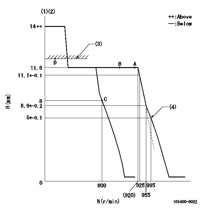
N:Pump speed
R:Rack position (mm)
(1)Target notch: K
(2)Tolerance for racks not indicated: +-0.05mm.
(3)RACK LIMIT
(4)Set idle sub-spring
----------
K=11
----------
----------
K=11
----------
Speed control lever angle

F:Full speed
I:Idle
(1)Stopper bolt setting
----------
----------
a=4deg+-5deg b=13deg+-5deg
----------
----------
a=4deg+-5deg b=13deg+-5deg
Stop lever angle
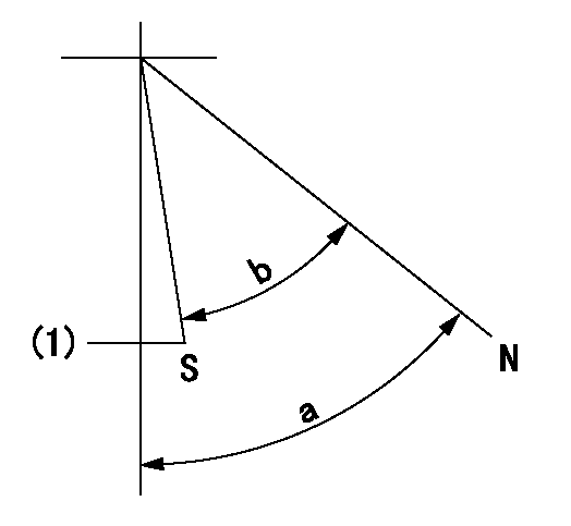
N:Pump normal
S:Stop the pump.
(1)Normal stop
----------
----------
a=58deg+-5deg b=53deg+-5deg
----------
----------
a=58deg+-5deg b=53deg+-5deg
Timing setting

(1)Pump vertical direction
(2)Position of camshaft's key groove at No 1 cylinder's beginning of injection
(3)-
(4)-
----------
----------
a=(60deg)
----------
----------
a=(60deg)
Information:
Dismantling And Installing The Camshaft (as from 3 cylinder engine)
Fasten engine in rotatable engine stand.Dismantling
4-561. Remove the rocker chamber covers and the rocker brackets. Take out the push-rods. Remove cooling blower, crankcase breather tube, oil pan and oil suction pipe with strainer.Fig. 4-56
4-572. Remove V-belt pulley and front cover. (Retainer for V-belt pulley No. 143400)Fig. 4-57 The V-belt pulley bolt has left-hand thread.
4-583. Remove oil pipe with oil pump. Take off idler gear with hub.Fig. 4-58
4-594. Pull out camshaft.Fig. 4-59Installing
1. Position the gearwheels with the marks lines up and carefully insert the camshaft with gear. Note that the marking on the injection pump gear differs, depending on the number of engine cylinder (3 cylinders, or 4, 5, 6 cylinders.)
4-60a) F3L: The reference mark on the injection pump gearwheel of this model is a figure 3 with a dot above it. Fig. 4-60
4-61b) F4/5/6L: Engines of these types have a dot to mark the mating point of the injection pump gearwheel.Fig. 4-61 Pay attention to modified marks on camshaft and injection pump gears.2. Fit a new rubber O-seal on the discharge pipe of the oil pump.3. Position the oil pump and pipe on the crankcase and tighten the oil pump screws. Adjust the gear flank clearance to the value stated in the specifications. The manufacturing material and tightening torque for the bolts fastening the lube oil pump have been changed.
4-624. Tighten and lock down the stud securing the idler gear mounting (on the oil delivery pipe clip), in accordance with the instructions for tightening bolts and studs.Fig. 4-62
4-635. Fit oil suction pipe with strainer.Fig. 4-63
4-646. Place compression spring and cap on camshaft spigot.Fig. 4-64
4-657. Fit a new gasket to the front cover, strick it in position with grease and mount the cover.Fig. 4-65
4-668. Grease the lip of the radial packing ring in the front cover and the contact surface of the vee-belt pulley. Install the vee-belt pulley, having brought the locating pin in the crankshaft gearwheel.Fig. 4-66
4-679. Screw in bolt (left-hand thread), preload and tighten as per instructions. (Retainer for V-belt pulley No. 143400, gauge No. 101910).Fig. 4-6710. Apply grease to a new gasket and stick it in position on the sump. Assemble the sump. Tightening torque for the oil drain plugs illustrated is: 150 Nm
4-6811. Fasten retainer for crankcase breather pipe at oil pan.Fig. 4-6812. Assemble the push-rods.
4-6913. Mount the rocker brackets. Tighten nuts as quoted in Specification Data.Fig. 4-69
4-7014. Adjust the valve clearance.Fig. 4-7015. Stick new gasket with sealing compound to rocker chamber cover. Position cover, align and fit bolt with new washer. Tightening see Specification Data.
4-7116. Align blower to holes and attach to front-end cover.Fig. 4-7117. Push idler pulley upward and install belt.18. Hook in the air cowling at the top and close at the bottom.Checking And Gauging The Crankshaft
1. Inspect crankshaft for cracks (by magnaflux method).2. Remove the gearwheel from the crankshaft.3. Support crankshaft at outer main journals on prism-shaped blocks.
4-724. Determine the hardness of the journal surfaces with a scleroscope. Conversions of the redlings