Information injection-pump assembly
BOSCH
9 400 611 653
9400611653
ZEXEL
101400-9021
1014009021

Rating:
Service parts 101400-9021 INJECTION-PUMP ASSEMBLY:
1.
_
4.
SUPPLY PUMP
5.
AUTOM. ADVANCE MECHANIS
6.
COUPLING PLATE
7.
COUPLING PLATE
8.
_
9.
_
10.
NOZZLE AND HOLDER ASSY
11.
Nozzle and Holder
12.
Open Pre:MPa(Kqf/cm2)
13.
NOZZLE-HOLDER
14.
NOZZLE
15.
NOZZLE SET
Cross reference number
BOSCH
9 400 611 653
9400611653
ZEXEL
101400-9021
1014009021
Zexel num
Bosch num
Firm num
Name
Calibration Data:
Adjustment conditions
Test oil
1404 Test oil ISO4113 or {SAEJ967d}
1404 Test oil ISO4113 or {SAEJ967d}
Test oil temperature
degC
40
40
45
Nozzle and nozzle holder
105780-8140
Bosch type code
EF8511/9A
Nozzle
105780-0000
Bosch type code
DN12SD12T
Nozzle holder
105780-2080
Bosch type code
EF8511/9
Opening pressure
MPa
17.2
Opening pressure
kgf/cm2
175
Injection pipe
Outer diameter - inner diameter - length (mm) mm 6-2-600
Outer diameter - inner diameter - length (mm) mm 6-2-600
Overflow valve
131424-1520
Overflow valve opening pressure
kPa
157
123
191
Overflow valve opening pressure
kgf/cm2
1.6
1.25
1.95
Tester oil delivery pressure
kPa
157
157
157
Tester oil delivery pressure
kgf/cm2
1.6
1.6
1.6
Direction of rotation (viewed from drive side)
Right R
Right R
Injection timing adjustment
Direction of rotation (viewed from drive side)
Right R
Right R
Injection order
1-3-4-2
Pre-stroke
mm
3.6
3.55
3.65
Beginning of injection position
Drive side NO.1
Drive side NO.1
Difference between angles 1
Cal 1-3 deg. 90 89.5 90.5
Cal 1-3 deg. 90 89.5 90.5
Difference between angles 2
Cal 1-4 deg. 180 179.5 180.5
Cal 1-4 deg. 180 179.5 180.5
Difference between angles 3
Cyl.1-2 deg. 270 269.5 270.5
Cyl.1-2 deg. 270 269.5 270.5
Injection quantity adjustment
Adjusting point
A
Rack position
11.6
Pump speed
r/min
900
900
900
Average injection quantity
mm3/st.
72
71
73
Max. variation between cylinders
%
0
-2.5
2.5
Basic
*
Fixing the lever
*
Injection quantity adjustment_02
Adjusting point
C
Rack position
8+-0.5
Pump speed
r/min
600
600
600
Average injection quantity
mm3/st.
11.5
10.5
12.5
Max. variation between cylinders
%
0
-15
15
Fixing the rack
*
Injection quantity adjustment_03
Adjusting point
D
Rack position
-
Pump speed
r/min
100
100
100
Average injection quantity
mm3/st.
75
70
80
Fixing the lever
*
Rack limit
*
Test data Ex:
Governor adjustment
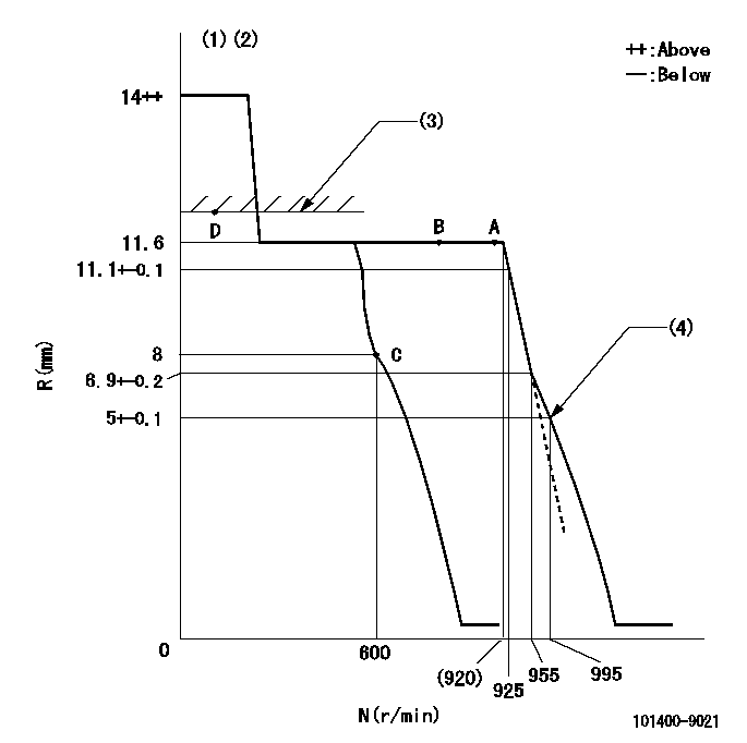
N:Pump speed
R:Rack position (mm)
(1)Target notch: K
(2)Tolerance for racks not indicated: +-0.05mm.
(3)RACK LIMIT
(4)Set idle sub-spring
----------
K=11
----------
----------
K=11
----------
Speed control lever angle

F:Full speed
I:Idle
(1)Stopper bolt setting
----------
----------
a=4deg+-5deg b=13deg+-5deg
----------
----------
a=4deg+-5deg b=13deg+-5deg
Stop lever angle
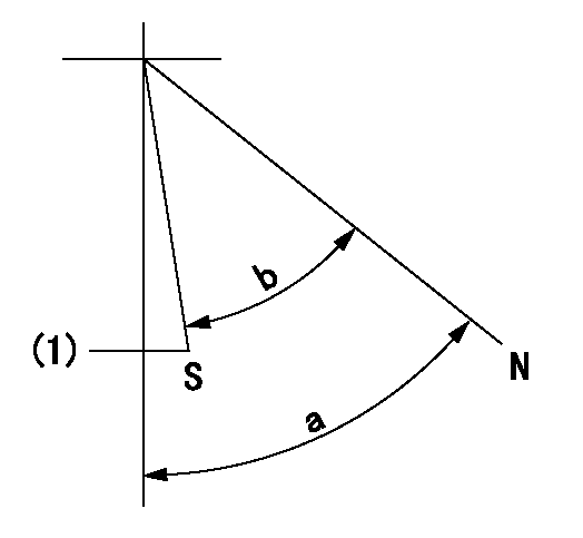
N:Pump normal
S:Stop the pump.
(1)At delivery
----------
----------
a=58deg+-5deg b=53deg+-5deg
----------
----------
a=58deg+-5deg b=53deg+-5deg
Timing setting

(1)Pump vertical direction
(2)Position of camshaft's key groove at No 1 cylinder's beginning of injection
(3)-
(4)-
----------
----------
a=(60deg)
----------
----------
a=(60deg)
Information:
Checking The Piston
1. If the cylinder is renewed, a new piston must be fitted. Normal and oversizes are given in the specifications.2. Inspect the piston for damage or visible wear, including the bosses.
3-613. Remove the compression rings and bevelled scraper ring. (Use piston-ring expander No. 130300)Fig. 3-61
3-624. Open and remove the expander spring for the bevelled scraper ring.Fig. 3-625. Clean the piston-ring grooves.
3-636. Measure axial piston ring clearance by using commercial tools.Fig. 3-63, leftMeasure first piston ring groove, if trapezoidal, by means of trapezoidal groove wear gauge No. 130360.Fig. 3-63, right
3-64 If, when measuring a piston with trapezoidal ring groove, a gap "S" (Fig. 3-64) is found to exist between the inserted gauge and the piston, this means that the axial piston ring clearance is within the tolerances stated in the Specification Data and the piston is fit for further use.
3-65But if the gauge contacts the side of the piston (see Fig. 3-65), i.e. without gap, the piston has to be renewed.
3-667. Insert all the piston rings singly in the cylinder and press down with the piston to a distance of 30 mm from the cylinder head contacting surface. Measure the gap clearance of the piston ring.Fig. 3-668. Compare the gap clearances of the piston rings with the values given in the specifications.9. Renew defective pistons together with gudgeon pin and rings. Renew also cylinders.
3-6710. When installing the piston rings start by fitting the expander spring for the bevelled scraper ring in the bottom groove.Fig. 3-67
3-6811. Assemble the piston rings with the aid of piston-ring expander No. 130300, in the following sequence:No. 3 (No. 4) Slotted, double-chamfered oil-control ring, chromium-plated.(No. 3) Tapered compression ring, ferrox finished; install with face marked "top" upwards.No. 2 Tapered compression ring, ferrox finished; install with face marked "top" upwards.No. 1 Top, double-trapezoidal compression ring, chromium-plated. "top" upwards.Fig. 3-68 Place the rings so that the gaps are evenly spaced around the piston.
3-6912. Check piston pin for wear using a bevelled steel straight edge or measuring angle, Fig. 3-69.
3-70 Secure the opposite end of the gudgeon pin in position. Place the piston on the small end of the connecting rod so that the exhaust air side of the piston (marked on the piston crown) is in the same direction as the open side of the connecting-rod bearing. Press in the gudgeon pin.Fig. 3-70Checking The Connecting Rod
Gauging and replacing piston pin bush
3-711. Set inside micrometer to starting dimension using a micrometer frame (see Technical Data).Fig. 3-71
3-722. Measure the piston pin bush at points one and two in the planes "a" and "b".Fig. 3-72 Attention:Compare recorded values with those specified in the Technical Data.
3-733. Pull out old piston pin bush with fixture No. 131310 and pull in new piston pin bush with the same device.Fig. 3-73
3-74 Note for installation:Pull in the new piston pin bush flush, making sure that the oil bores in bush and connecting rod coincide.Fig. 3-74Gauging And Replacing Big-End Bearings
3-75The big-end bearings are of finished type. They are made of two half