Information injection-pump assembly
BOSCH
9 400 611 780
9400611780
ZEXEL
101342-9070
1013429070
Rating:
Service parts 101342-9070 INJECTION-PUMP ASSEMBLY:
1.
_
5.
AUTOM. ADVANCE MECHANIS
6.
COUPLING PLATE
8.
_
9.
_
10.
NOZZLE AND HOLDER ASSY
11.
Nozzle and Holder
12.
Open Pre:MPa(Kqf/cm2)
11.8{120}

15.
NOZZLE SET
Cross reference number
BOSCH
9 400 611 780
9400611780
ZEXEL
101342-9070
1013429070
Zexel num
Bosch num
Firm num
Name
101342-9070
9 400 611 780
DAEWOO
INJECTION-PUMP ASSEMBLY
3AB1 * K
3AB1 * K
Calibration Data:
Adjustment conditions
Test oil
1404 Test oil ISO4113 or {SAEJ967d}
1404 Test oil ISO4113 or {SAEJ967d}
Test oil temperature
degC
40
40
45
Nozzle and nozzle holder
105780-8140
Bosch type code
EF8511/9A
Nozzle
105780-0000
Bosch type code
DN12SD12T
Nozzle holder
105780-2080
Bosch type code
EF8511/9
Opening pressure
MPa
17.2
Opening pressure
kgf/cm2
175
Injection pipe
Outer diameter - inner diameter - length (mm) mm 6-2-600
Outer diameter - inner diameter - length (mm) mm 6-2-600
Tester oil delivery pressure
kPa
157
157
157
Tester oil delivery pressure
kgf/cm2
1.6
1.6
1.6
Direction of rotation (viewed from drive side)
Left L
Left L
Injection timing adjustment
Direction of rotation (viewed from drive side)
Left L
Left L
Injection order
1-3-2
Pre-stroke
mm
1.95
1.9
2
Beginning of injection position
Drive side NO.1
Drive side NO.1
Difference between angles 1
Cal 1-3 deg. 120 119.5 120.5
Cal 1-3 deg. 120 119.5 120.5
Difference between angles 2
Cyl.1-2 deg. 240 239.5 240.5
Cyl.1-2 deg. 240 239.5 240.5
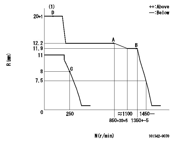
Injection quantity adjustment
Adjusting point
A
Rack position
12.2
Pump speed
r/min
850
850
850
Average injection quantity
mm3/st.
39
37.9
40.1
Max. variation between cylinders
%
0
-2.5
2.5
Basic
*
Fixing the lever
*
Injection quantity adjustment_02
Adjusting point
B
Rack position
11.9
Pump speed
r/min
1300
1300
1300
Average injection quantity
mm3/st.
42.3
40.8
43.8
Max. variation between cylinders
%
0
-4
4
Fixing the lever
*
Injection quantity adjustment_03
Adjusting point
-
Rack position
8.5+-0.5
Pump speed
r/min
250
250
250
Average injection quantity
mm3/st.
9
7.7
10.3
Max. variation between cylinders
%
0
-14
14
Fixing the rack
*
Remarks
Adjust only variation between cylinders; adjust governor according to governor specifications.
Adjust only variation between cylinders; adjust governor according to governor specifications.
Injection quantity adjustment_04
Adjusting point
D
Rack position
-
Pump speed
r/min
150
150
150
Average injection quantity
mm3/st.
66.3
66.3
Fixing the lever
*
Test data Ex:
Governor adjustment
N:Pump speed
R:Rack position (mm)
(1)Target notch: K
----------
K=15
----------
----------
K=15
----------
Speed control lever angle

F:Full speed
I:Idle
(1)Stopper bolt setting
----------
----------
a=18.5deg+-5deg b=33deg+-5deg
----------
----------
a=18.5deg+-5deg b=33deg+-5deg
Stop lever angle

N:Pump normal
S:Stop the pump.
----------
----------
a=19deg+-5deg b=53deg+-5deg
----------
----------
a=19deg+-5deg b=53deg+-5deg
Timing setting

(1)Pump vertical direction
(2)Position of gear mark 'Z' at No 1 cylinder's beginning of injection
(3)B.T.D.C.: aa
(4)-
----------
aa=18deg
----------
a=(120deg)
----------
aa=18deg
----------
a=(120deg)
Information:
Climbing equipment may be required to access this service point. Refer to the Operation and Maintenance Manual, "Mounting and Dismounting" topic for safety information.
Before servicing/performing maintenance on the machine, electrical power must be physically disconnected; battery plugs must be disconnected from the batteries, or the trailing cable must be unplugged, and warning tags and padlocks shall be applied by a certified electrician. Certified electricians shall perform or direct any electrical work, including any energized testing, repair work in controllers, motors, or other approved compartments, and shall insure that all compartments are properly closed and inspected prior to re-energization. All applicable lock out and tag out procedures must be followed.
Observe the safe working load limits of all lifting and blocking devices and keep a safe distance from suspended/blocked loads. Personnel may be seriously injured or killed by falling loads.
Required Parts
The LFI component PMMA surface characteristics are as follows
Cover Layer
Gloss
Scratch resistance
Weather resistance
Color Layer
Coloring
Ultraviolet resistance
Carrier Layer
Adhesion to backing foam
Heat deformation resistance
Backing Foam
Strength
Stability
Impact resistance
Heat deformation resistanceRepair Procedure
Illustration 1 g06509785
Simulated punch hole
Illustration 2 g06509787
Location to grind off backside
Grind material off from backside
Illustration 3 g06509788
Fiberglass mat and plastic filler
Place fiberglass mat and place plastic filler on backside
Illustration 4 g06509791
Location to grind off exterior side
Grind material off from exterior side
Illustration 5 g06509792
Location to add filler on exterior side
Fill hole on exterior side with plastic filler
Illustration 6 g06510059
Exterior surface to grind flat
Grind plastic filler on exterior to achieve flat surface
Illustration 7 g06510075
Area to apply plasticiser
Apply plastic filler with plasticiser to the exterior
Illustration 8 g06510079
Exterior area to grind plastic filler containing plasticiser
Grind plastic filler containing plasticiser and also area to be painted
Illustration 9 g06510084
Exterior plastic surface painted with primer
Paint exterior with primer for plastic surfaces
Illustration 10 g06510086
Exterior plastic surface painted with top coat
Paint exterior with top coat
Have questions with 101342-9070?
Group cross 101342-9070 ZEXEL
Toyo-Sha
Iseki
Daewoo
101342-9070
9 400 611 780
INJECTION-PUMP ASSEMBLY
3AB1
3AB1