Information injection-pump assembly
ZEXEL
101342-0411
1013420411
ISUZU
8970103881
8970103881
Rating:
Cross reference number
ZEXEL
101342-0411
1013420411
ISUZU
8970103881
8970103881
Zexel num
Bosch num
Firm num
Name
Calibration Data:
Adjustment conditions
Test oil
1404 Test oil ISO4113 or {SAEJ967d}
1404 Test oil ISO4113 or {SAEJ967d}
Test oil temperature
degC
40
40
45
Nozzle and nozzle holder
105780-8140
Bosch type code
EF8511/9A
Nozzle
105780-0000
Bosch type code
DN12SD12T
Nozzle holder
105780-2080
Bosch type code
EF8511/9
Opening pressure
MPa
17.2
Opening pressure
kgf/cm2
175
Injection pipe
Outer diameter - inner diameter - length (mm) mm 6-2-600
Outer diameter - inner diameter - length (mm) mm 6-2-600
Tester oil delivery pressure
kPa
157
157
157
Tester oil delivery pressure
kgf/cm2
1.6
1.6
1.6
Direction of rotation (viewed from drive side)
Left L
Left L
Injection timing adjustment
Direction of rotation (viewed from drive side)
Left L
Left L
Injection order
1-3-2
Pre-stroke
mm
1.95
1.9
2
Beginning of injection position
Drive side NO.1
Drive side NO.1
Difference between angles 1
Cal 1-3 deg. 120 119.5 120.5
Cal 1-3 deg. 120 119.5 120.5
Difference between angles 2
Cyl.1-2 deg. 240 239.5 240.5
Cyl.1-2 deg. 240 239.5 240.5
Injection quantity adjustment
Adjusting point
A
Rack position
11.7
Pump speed
r/min
1200
1200
1200
Average injection quantity
mm3/st.
42.3
41.5
43.1
Max. variation between cylinders
%
0
-2
2
Basic
*
Fixing the lever
*
Injection quantity adjustment_02
Adjusting point
-
Rack position
7.6+-0.5
Pump speed
r/min
360
360
360
Average injection quantity
mm3/st.
8
7
9
Max. variation between cylinders
%
0
-14
14
Fixing the rack
*
Remarks
Adjust only variation between cylinders; adjust governor according to governor specifications.
Adjust only variation between cylinders; adjust governor according to governor specifications.
Test data Ex:
Governor adjustment
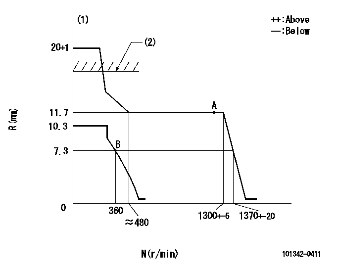
N:Pump speed
R:Rack position (mm)
(1)Target notch: K
(2)RACK CAP: R1
----------
K=10 R1=(17.5)mm
----------
----------
K=10 R1=(17.5)mm
----------
Speed control lever angle
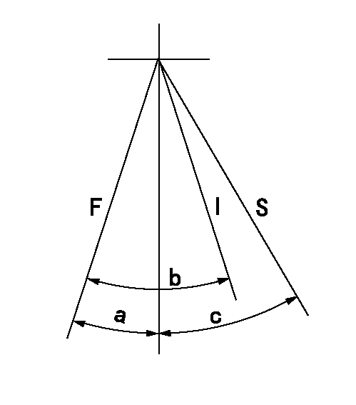
F:Full speed
I:Idle
S:Stop
----------
----------
a=16.5deg+-5deg b=30.5deg+-5deg c=32deg+-3deg
----------
----------
a=16.5deg+-5deg b=30.5deg+-5deg c=32deg+-3deg
Stop lever angle

N:Pump normal
S:Stop the pump.
----------
----------
a=19deg+-5deg b=53deg+-5deg
----------
----------
a=19deg+-5deg b=53deg+-5deg
Timing setting

(1)Pump vertical direction
(2)Position of gear mark 'Z' at No 1 cylinder's beginning of injection
(3)B.T.D.C.: aa
(4)-
----------
aa=18deg
----------
a=(120deg)
----------
aa=18deg
----------
a=(120deg)
Information:
Do not operate or work on this product unless you have read and understood the instruction and warnings in the relevant Operation and Maintenance Manuals and relevant service literature. Failure to follow the instructions or heed the warnings could result in injury or death. Proper care is your responsibility.
The following changes are adaptable to the products within the listed serial numbers, and are effective with all products after the listed serial numbers.The table below contains the new fuel injector part numbers.Note: Use a 563-8152 Engine Oil Filter (High Efficiency) along with the new fuel injectors.
Table 1
Required Parts
Item Qty New Part Number Part Name
1 6 387-9426 Fuel Injector Gp
2 6 387-9428 Fuel Injector Gp
3 6 387-9429 Fuel Injector Gp
4 6 387-9430 Fuel Injector Gp
5 6 387-9432 Fuel Injector Gp
6 6 387-9434 Fuel Injector Gp
7 6 387-9436 Fuel Injector Gp
8 6 387-9437 Fuel Injector Gp
9 6 387-9438 Fuel Injector Gp
10 6 387-9439 Fuel Injector Gp
11 6 387-9440 Fuel Injector Gp
12 6 387-9441 Fuel Injector Gp
13 6 557-7627 Fuel Injector Gp
14 6 557-7633 Fuel Injector Gp
15 1 563-8152 Engine Oil Filter
16 6 573-4231 Fuel Injector Gp
17 6 573-4235 Fuel Injector Gp The effective serial number for the improved fuel injectors is 3B142289137E.