Information injection-pump assembly
BOSCH
9 400 613 532
9400613532
ZEXEL
101342-0400
1013420400
ISUZU
8944660850
8944660850
Rating:
Service parts 101342-0400 INJECTION-PUMP ASSEMBLY:
1.
_
5.
AUTOM. ADVANCE MECHANIS
6.
COUPLING PLATE
8.
_
9.
_
11.
Nozzle and Holder
12.
Open Pre:MPa(Kqf/cm2)
11.8{120}

15.
NOZZLE SET
Cross reference number
BOSCH
9 400 613 532
9400613532
ZEXEL
101342-0400
1013420400
ISUZU
8944660850
8944660850
Zexel num
Bosch num
Firm num
Name
101342-0400
9 400 613 532
8944660850 ISUZU
INJECTION-PUMP ASSEMBLY
3AB1 K 14BA INJECTION PUMP ASSY PE1A,2A,3A PE
3AB1 K 14BA INJECTION PUMP ASSY PE1A,2A,3A PE
Calibration Data:
Adjustment conditions
Test oil
1404 Test oil ISO4113 or {SAEJ967d}
1404 Test oil ISO4113 or {SAEJ967d}
Test oil temperature
degC
40
40
45
Nozzle and nozzle holder
105780-8140
Bosch type code
EF8511/9A
Nozzle
105780-0000
Bosch type code
DN12SD12T
Nozzle holder
105780-2080
Bosch type code
EF8511/9
Opening pressure
MPa
17.2
Opening pressure
kgf/cm2
175
Injection pipe
Outer diameter - inner diameter - length (mm) mm 6-2-600
Outer diameter - inner diameter - length (mm) mm 6-2-600
Tester oil delivery pressure
kPa
157
157
157
Tester oil delivery pressure
kgf/cm2
1.6
1.6
1.6
Direction of rotation (viewed from drive side)
Left L
Left L
Injection timing adjustment
Direction of rotation (viewed from drive side)
Left L
Left L
Injection order
1-3-2
Pre-stroke
mm
1.95
1.9
2
Beginning of injection position
Drive side NO.1
Drive side NO.1
Difference between angles 1
Cal 1-3 deg. 120 119.5 120.5
Cal 1-3 deg. 120 119.5 120.5
Difference between angles 2
Cyl.1-2 deg. 240 239.5 240.5
Cyl.1-2 deg. 240 239.5 240.5
Injection quantity adjustment
Adjusting point
B
Rack position
12.2
Pump speed
r/min
900
900
900
Average injection quantity
mm3/st.
43
42
44
Max. variation between cylinders
%
0
-2
2
Basic
*
Fixing the lever
*
Injection quantity adjustment_02
Adjusting point
-
Rack position
7.6+-0.5
Pump speed
r/min
475
475
475
Average injection quantity
mm3/st.
8
7
9
Max. variation between cylinders
%
0
-14
14
Fixing the rack
*
Remarks
Adjust only variation between cylinders; adjust governor according to governor specifications.
Adjust only variation between cylinders; adjust governor according to governor specifications.
Test data Ex:
Governor adjustment
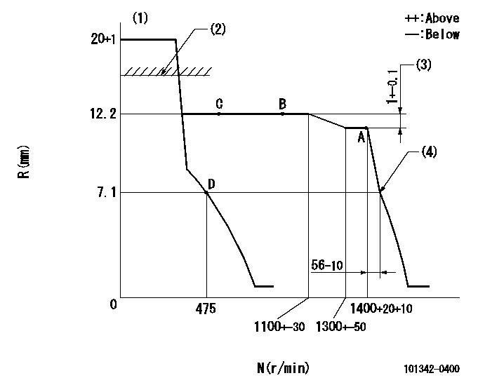
N:Pump speed
R:Rack position (mm)
(1)Target notch: K
(2)RACK CAP: R1
(3)Rack difference between N = N1 and N = N2
(4)Idle sub spring setting: L1.
----------
K=5 R1=(17.5)mm N1=1400r/min N2=900r/min L1=6.9-0.2mm
----------
----------
K=5 R1=(17.5)mm N1=1400r/min N2=900r/min L1=6.9-0.2mm
----------
Speed control lever angle

F:Full speed
I:Idle
(1)Stopper bolt setting
----------
----------
a=9deg+-5deg b=25deg+-5deg
----------
----------
a=9deg+-5deg b=25deg+-5deg
Stop lever angle

N:Pump normal
S:Stop the pump.
----------
----------
a=19deg+-5deg b=53deg+-5deg
----------
----------
a=19deg+-5deg b=53deg+-5deg
Timing setting

(1)Pump vertical direction
(2)Position of gear mark 'Z' at No 1 cylinder's beginning of injection
(3)B.T.D.C.: aa
(4)-
----------
aa=18deg
----------
a=(120deg)
----------
aa=18deg
----------
a=(120deg)
Information:
Solution
Do not operate or work on this product unless you have read and understood the instruction and warnings in the relevant Operation and Maintenance Manuals and relevant service literature. Failure to follow the instructions or heed the warnings could result in injury or death. Proper care is your responsibility.
Note: Only perform these troubleshooting steps when the DEF tank is fully thawed and there is no remaining ice crystals/slush in the tank.Note: If any of the troubleshooting indicates the replacement of the DEF manifold, do not replace the DEF manifold. Repair the DEF manifold using the DEF manifold sensor kit.
Use the electronic service tool to download a full Product Status Report (PSR) (including all histograms and histories) before performing any troubleshooting.
Review the PSR to determine which code/events recorded have led to the activation SCR inducement codes:Note: Check the "Aftertreatment Abnormal Shutdown History" for Hot/Cold Shutdown events which may have occurred prior to the current inducement situation and may be an indication the system was incorrectly shut down previously.
A Cold Shutdown is recorded when the ambient temp is below −5° C (23° F) and the system has not completed the cooldown and system purge during the previous key-cycle.
Only investigate a logged 1235-9 (5856-9) code if the code has occurred less than 5 hours prior to the current diagnostic clock value. If the code is not persistent, the code is likely to be generated by either old engine software or a power supply dropping below the min supply voltage. If the code is showing a persistent triggering when on the latest engine software, this condition would indicate a hardware/connection issue.
DEF level codes (1761-xx/E954) are not to be considered a sign of DEF Manifold hardware failure (especially when in low ambient temperatures) unless the codes remain persistent after a tank fill. If there is another code present such as 1761-2/3130-2 (DEF level – Erratic) or 5392-31/E1370 (DEF Loss of Prime), this condition would indicate a system level issue, or the DEF tank has recently been fully drained down for an extended period and may require time for any DEF deposits to dissolve before level readings stabilize.
The order of troubleshooting codes should be SCR Inducement last, with DEF Tank Level codes second from last, always troubleshooting the DEF Volume Erratic (1761-2/3130-2) or DEF – Loss of Prime (5392-31/E1370) codes first.
Prior to beginning any troubleshooting of the codes reviewed in Step 2 and based on analysis, check that the coolant diverter valve is functioning correctly. Not allowing a small coolant flow to heat DEF tank fluid unintentionally above ambient temperature without triggering any codes, refer to Troubleshooting, DEF Tank Temperature Is High.
Ensure that the coolant flow direction is aligned with the flow direction arrow valve on the valve body. Refer to Step 3civ.
Record the ambient air temperature and DEF tank fluid temperature prior to starting the engine. Use these temperature readings as the reference for determining a temperature increase after warming the engine at idle. Refer to Step6.Note: As DEF is used as the
Have questions with 101342-0400?
Group cross 101342-0400 ZEXEL
Isuzu
101342-0400
9 400 613 532
8944660850
INJECTION-PUMP ASSEMBLY
3AB1
3AB1