Information injection-pump assembly
BOSCH
9 400 613 531
9400613531
ZEXEL
101342-0390
1013420390
ISUZU
8944681320
8944681320

Rating:
Service parts 101342-0390 INJECTION-PUMP ASSEMBLY:
1.
_
5.
AUTOM. ADVANCE MECHANIS
6.
COUPLING PLATE
8.
_
9.
_
11.
Nozzle and Holder
12.
Open Pre:MPa(Kqf/cm2)
11.8(120)

15.
NOZZLE SET
Cross reference number
BOSCH
9 400 613 531
9400613531
ZEXEL
101342-0390
1013420390
ISUZU
8944681320
8944681320
Zexel num
Bosch num
Firm num
Name
101342-0390
9 400 613 531
8944681320 ISUZU
INJECTION-PUMP ASSEMBLY
3AB1 * K 14BA PE1A,2A,3A PE
3AB1 * K 14BA PE1A,2A,3A PE
Calibration Data:
Adjustment conditions
Test oil
1404 Test oil ISO4113 or {SAEJ967d}
1404 Test oil ISO4113 or {SAEJ967d}
Test oil temperature
degC
40
40
45
Nozzle and nozzle holder
105780-8140
Bosch type code
EF8511/9A
Nozzle
105780-0000
Bosch type code
DN12SD12T
Nozzle holder
105780-2080
Bosch type code
EF8511/9
Opening pressure
MPa
17.2
Opening pressure
kgf/cm2
175
Injection pipe
Outer diameter - inner diameter - length (mm) mm 6-2-600
Outer diameter - inner diameter - length (mm) mm 6-2-600
Tester oil delivery pressure
kPa
157
157
157
Tester oil delivery pressure
kgf/cm2
1.6
1.6
1.6
Direction of rotation (viewed from drive side)
Left L
Left L
Injection timing adjustment
Direction of rotation (viewed from drive side)
Left L
Left L
Injection order
1-3-2
Pre-stroke
mm
1.95
1.9
2
Beginning of injection position
Drive side NO.1
Drive side NO.1
Difference between angles 1
Cal 1-3 deg. 120 119.5 120.5
Cal 1-3 deg. 120 119.5 120.5
Difference between angles 2
Cyl.1-2 deg. 240 239.5 240.5
Cyl.1-2 deg. 240 239.5 240.5
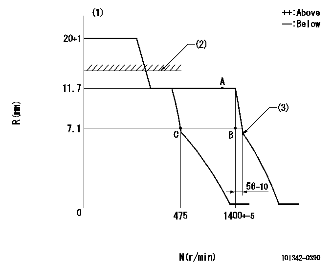
Injection quantity adjustment
Adjusting point
A
Rack position
11.7
Pump speed
r/min
1200
1200
1200
Average injection quantity
mm3/st.
43
42.2
43.8
Max. variation between cylinders
%
0
-2
2
Basic
*
Fixing the rack
*
Injection quantity adjustment_02
Adjusting point
B
Rack position
7.1
Pump speed
r/min
1400
1400
1400
Average injection quantity
mm3/st.
13.1
12.2
14
Max. variation between cylinders
%
0
-8
8
Fixing the rack
*
Injection quantity adjustment_03
Adjusting point
C
Rack position
7.1+-0.5
Pump speed
r/min
475
475
475
Average injection quantity
mm3/st.
6
5
7
Max. variation between cylinders
%
0
-14
14
Fixing the rack
*
Test data Ex:
Governor adjustment
N:Pump speed
R:Rack position (mm)
(1)Target notch: K
(2)RACK LIMIT: RAL
(3)Idle sub spring setting: L1.
----------
K=3 RAL=(17.5)mm L1=6.9-0.2mm
----------
----------
K=3 RAL=(17.5)mm L1=6.9-0.2mm
----------
Speed control lever angle

F:Full speed
I:Idle
(1)Stopper bolt setting
----------
----------
a=10deg+-5deg b=28.5deg+-5deg
----------
----------
a=10deg+-5deg b=28.5deg+-5deg
Stop lever angle
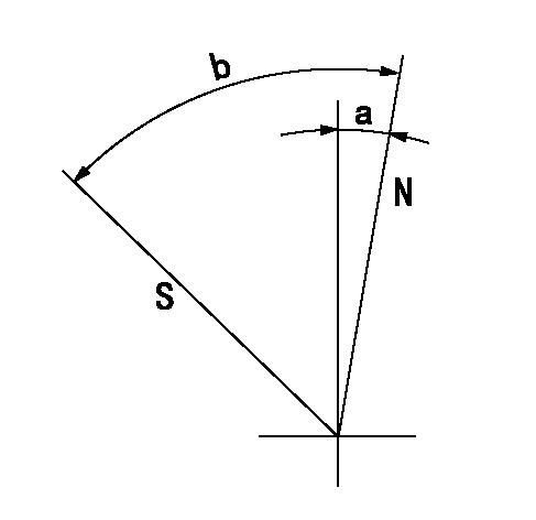
N:Pump normal
S:Stop the pump.
----------
----------
a=2.5deg+-5deg b=53deg+-5deg
----------
----------
a=2.5deg+-5deg b=53deg+-5deg
Timing setting

(1)Pump vertical direction
(2)Position of gear mark 'Z' at No 1 cylinder's beginning of injection
(3)B.T.D.C.: aa
(4)-
----------
aa=18deg
----------
a=(120deg)
----------
aa=18deg
----------
a=(120deg)
Information:
Table 1
Item 3408C / 3412C 3176B 3176C / 3196
Connector P14 P1 P1
(-) Battery Pin-21 Pin-5 Pin-5
(+) 8 VDC Pin-10 Pin-35 Pin-35
Cat Data (+) Pin-9 Pin-9 Pin-9
Cat Data (-) Pin-19 Pin-3 Pin-3
Illustration 1 g06449052
(A) Port ECM
(B) Cat Link Booster
(C) EVIM
(D) STBD ECM
(E) CAT Link Booster
(F) Engine Vision Display
Illustration 2 g06449056
(G) Connector A
(H) Connector B
Turn the power OFF to the engine ECM and display unit.
Remove the ECM connector-battery pin and reinsert it into pin-3 on the 4-pin DT connector B (2).
Remove the ECM connector +8 VDC pin and reinsert into pin-4 on the 4-pin DT connector B (2).
Remove the ECM connector (CAT Data+) pin and reinsert into pin-1 on the 4-pin DT connector B (2).
Remove the ECM connector (Cat Data-) pin and reinsert into pin-2 on the 4-pin DT connector B (2).
Insert the BLACK wire into the ECM connector-battery pin.
Insert the PINK wire into the ECM connector CAT Data+ pin.
Insert the WHITE wire into the ECM connector CAT Data- pin.
Insert the RED wire into the ECM connector +8 VDC supply pin.
Plug connector B (2) into connector A (1).
Apply power to the ECM.
Have questions with 101342-0390?
Group cross 101342-0390 ZEXEL
Isuzu
101342-0390
9 400 613 531
8944681320
INJECTION-PUMP ASSEMBLY
3AB1
3AB1