Information injection-pump assembly
ZEXEL
101342-0350
1013420350
ISUZU
8941715050
8941715050

Rating:
Service parts 101342-0350 INJECTION-PUMP ASSEMBLY:
1.
_
5.
AUTOM. ADVANCE MECHANIS
6.
COUPLING PLATE
8.
_
9.
_
10.
NOZZLE AND HOLDER ASSY
11.
Nozzle and Holder
12.
Open Pre:MPa(Kqf/cm2)
11.8(120)

15.
NOZZLE SET
Cross reference number
ZEXEL
101342-0350
1013420350
ISUZU
8941715050
8941715050
Zexel num
Bosch num
Firm num
Name
Calibration Data:
Adjustment conditions
Test oil
1404 Test oil ISO4113 or {SAEJ967d}
1404 Test oil ISO4113 or {SAEJ967d}
Test oil temperature
degC
40
40
45
Nozzle and nozzle holder
105780-8140
Bosch type code
EF8511/9A
Nozzle
105780-0000
Bosch type code
DN12SD12T
Nozzle holder
105780-2080
Bosch type code
EF8511/9
Opening pressure
MPa
17.2
Opening pressure
kgf/cm2
175
Injection pipe
Outer diameter - inner diameter - length (mm) mm 6-2-600
Outer diameter - inner diameter - length (mm) mm 6-2-600
Tester oil delivery pressure
kPa
157
157
157
Tester oil delivery pressure
kgf/cm2
1.6
1.6
1.6
Direction of rotation (viewed from drive side)
Left L
Left L
Injection timing adjustment
Direction of rotation (viewed from drive side)
Left L
Left L
Injection order
1-3-2
Pre-stroke
mm
1.95
1.9
2
Beginning of injection position
Drive side NO.1
Drive side NO.1
Difference between angles 1
Cal 1-3 deg. 120 119.5 120.5
Cal 1-3 deg. 120 119.5 120.5
Difference between angles 2
Cyl.1-2 deg. 240 239.5 240.5
Cyl.1-2 deg. 240 239.5 240.5
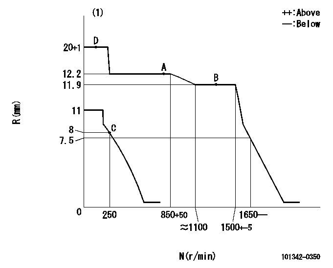
Injection quantity adjustment
Adjusting point
A
Rack position
12.2
Pump speed
r/min
850
850
850
Average injection quantity
mm3/st.
39
37.9
40.1
Max. variation between cylinders
%
0
-2.5
2.5
Basic
*
Fixing the lever
*
Injection quantity adjustment_02
Adjusting point
B
Rack position
11.9
Pump speed
r/min
1300
1300
1300
Average injection quantity
mm3/st.
42.3
40.8
43.8
Max. variation between cylinders
%
0
-4
4
Fixing the lever
*
Injection quantity adjustment_03
Adjusting point
-
Rack position
8.5+-0.5
Pump speed
r/min
250
250
250
Average injection quantity
mm3/st.
9
7.7
10.3
Max. variation between cylinders
%
0
-14
14
Fixing the rack
*
Remarks
Adjust only variation between cylinders; adjust governor according to governor specifications.
Adjust only variation between cylinders; adjust governor according to governor specifications.
Injection quantity adjustment_04
Adjusting point
D
Rack position
-
Pump speed
r/min
150
150
150
Average injection quantity
mm3/st.
66.3
66.3
Fixing the lever
*
Test data Ex:
Governor adjustment
N:Pump speed
R:Rack position (mm)
(1)Target notch: K
----------
K=15
----------
----------
K=15
----------
Speed control lever angle
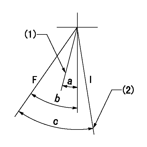
F:Full speed
I:Idle
(1)Cancel spring dead point
(2)Stopper bolt setting
----------
----------
a=(10deg) b=28deg+-5deg c=32deg+-5deg
----------
----------
a=(10deg) b=28deg+-5deg c=32deg+-5deg
Stop lever angle

N:Pump normal
S:Stop the pump.
----------
----------
a=19deg+-5deg b=53deg+-5deg
----------
----------
a=19deg+-5deg b=53deg+-5deg
Timing setting

(1)Pump vertical direction
(2)Position of gear mark 'Z' at No 1 cylinder's beginning of injection
(3)B.T.D.C.: aa
(4)-
----------
aa=22deg
----------
a=(120deg)
----------
aa=22deg
----------
a=(120deg)
Information:
Installation Instructions
Using the PC, copy the file called amupdate.img to the USB stick. Make sure that the file is located directly on the USB stick and not saved in any directory on the USB stick.
Take note of the current Kernel version of the unit (if possible).
Disconnect the supply power to the unit to be upgraded.
Insert the USB stick at the back of the unit.
Reconnect the supply power to the unit and observe brief block of text message on the display, as the new kernel is being uploaded and installed. (This message is only shown for a few seconds.)
Wait for the unit to start up fully. Dismiss the USB Storage form, if shown, and remove the USB stick from the unit.
Check the Kernel version and verify that Kernel version is "180820".