Information injection-pump assembly
BOSCH
9 400 611 140
9400611140
ZEXEL
101342-0260
1013420260
ISUZU
5156009423
5156009423
Rating:
Service parts 101342-0260 INJECTION-PUMP ASSEMBLY:
1.
_
5.
AUTOM. ADVANCE MECHANIS
6.
COUPLING PLATE
8.
_
9.
_
11.
Nozzle and Holder
12.
Open Pre:MPa(Kqf/cm2)
11.8{120}

15.
NOZZLE SET
Cross reference number
BOSCH
9 400 611 140
9400611140
ZEXEL
101342-0260
1013420260
ISUZU
5156009423
5156009423
Zexel num
Bosch num
Firm num
Name
101342-0260
9 400 611 140
5156009423 ISUZU
INJECTION-PUMP ASSEMBLY
3AB1 * K 14BA PE1A,2A,3A PE
3AB1 * K 14BA PE1A,2A,3A PE
Calibration Data:
Adjustment conditions
Test oil
1404 Test oil ISO4113 or {SAEJ967d}
1404 Test oil ISO4113 or {SAEJ967d}
Test oil temperature
degC
40
40
45
Nozzle and nozzle holder
105780-8140
Bosch type code
EF8511/9A
Nozzle
105780-0000
Bosch type code
DN12SD12T
Nozzle holder
105780-2080
Bosch type code
EF8511/9
Opening pressure
MPa
17.2
Opening pressure
kgf/cm2
175
Injection pipe
Outer diameter - inner diameter - length (mm) mm 6-2-600
Outer diameter - inner diameter - length (mm) mm 6-2-600
Tester oil delivery pressure
kPa
157
157
157
Tester oil delivery pressure
kgf/cm2
1.6
1.6
1.6
Direction of rotation (viewed from drive side)
Left L
Left L
Injection timing adjustment
Direction of rotation (viewed from drive side)
Left L
Left L
Injection order
1-3-2
Pre-stroke
mm
1.95
1.9
2
Beginning of injection position
Drive side NO.1
Drive side NO.1
Difference between angles 1
Cal 1-3 deg. 120 119.5 120.5
Cal 1-3 deg. 120 119.5 120.5
Difference between angles 2
Cyl.1-2 deg. 240 239.5 240.5
Cyl.1-2 deg. 240 239.5 240.5
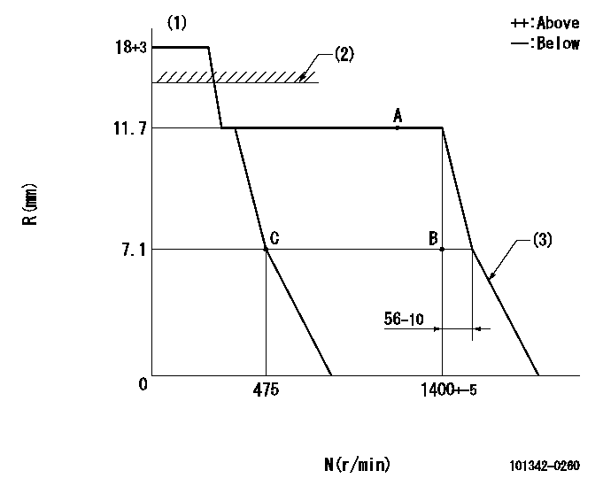
Injection quantity adjustment
Adjusting point
A
Rack position
11.7
Pump speed
r/min
1200
1200
1200
Average injection quantity
mm3/st.
43
42.2
43.8
Max. variation between cylinders
%
0
-2
2
Basic
*
Fixing the rack
*
Injection quantity adjustment_02
Adjusting point
B
Rack position
7.1
Pump speed
r/min
1400
1400
1400
Average injection quantity
mm3/st.
13.1
12.2
14
Max. variation between cylinders
%
0
-8
8
Fixing the rack
*
Injection quantity adjustment_03
Adjusting point
C
Rack position
7.1+-0.5
Pump speed
r/min
475
475
475
Average injection quantity
mm3/st.
6
5
7
Max. variation between cylinders
%
0
-14
14
Fixing the rack
*
Test data Ex:
Governor adjustment
N:Pump speed
R:Rack position (mm)
(1)Target notch: K
(2)RACK LIMIT: RAL
(3)Idle sub spring setting: L1.
----------
K=3 RAL=(17.5)mm L1=6.9-0.2mm
----------
----------
K=3 RAL=(17.5)mm L1=6.9-0.2mm
----------
Speed control lever angle

F:Full speed
I:Idle
(1)Stopper bolt setting
----------
----------
a=10deg+-5deg b=28.5deg+-5deg
----------
----------
a=10deg+-5deg b=28.5deg+-5deg
Stop lever angle
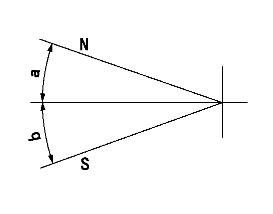
N:Pump normal
S:Stop the pump.
----------
----------
a=(19deg) b=(34deg)
----------
----------
a=(19deg) b=(34deg)
Timing setting

(1)Pump vertical direction
(2)Position of gear mark 'Z' at No 1 cylinder's beginning of injection
(3)B.T.D.C.: aa
(4)-
----------
aa=18deg
----------
a=(120deg)
----------
aa=18deg
----------
a=(120deg)
Information:
Personal injury can result from improper handling of chemicals.Make sure you use all the necessary protective equipment required to do the job.Make sure that you read and understand all directions and hazards described on the labels and material safety data sheet of any chemical that is used.Observe all safety precautions recommended by the chemical manufacturer for handling, storage, and disposal of chemicals.
C175 Engine References
Reference: Troubleshooting, M0069788, "C175 Tier 4 Final Engines for Off-Highway Trucks"Reference: Testing and Adjusting, M0069782, "C175 Tier 4 Final Engines for Off-Highway Trucks"Reference: Disassembly and Assembly, M0080117, "C175 Tier 4 Final Engines for Caterpillar Built Machines"3500 Engine References
Reference: Troubleshooting, M0080819, "3516E Engine for Tier 4 Final 994K Wheel Loaders"Reference: Testing and Adjusting, M0080815, "3516E Engine for Tier 4 Final 994K Wheel Loaders"Reference: Disassembly and Assembly, M0092351, "3516E Engines for Caterpillar Built Machines"Procedure
Note: If failed parts need to be shipped back, please cap off the ports using the caps from the new part.
The DEF injector troubleshooting return form is required and included with failed part returns documenting what was found that led to DEF injector replacement. Attach photos of the DEF injector tip and the mount area along with a Product Status Report to the Service Information Management System claim.
Determine the diagnostic code. ____________________
Troubleshoot the code found using the appropriate troubleshooting manual.
When the troubleshooting procedure requests the DEF quality check, DEF injector resistance measurement, or Dosing Accuracy Test, document the results in Tables 1, 2, and 3.
Table 1
DEF Quality Results
Step Instruction Completed (Yes/No) Units
1 Follow the Testing and Adjusting procedure for "Diesel Exhaust Fluid Quality - Test"
2 DEF Contamination Test (include photo of test strip if possible)
3 DEF Concentration Test
% at 20° C (68° F)
Illustration 1 g06371891
Diesel Exhaust Fluid (DEF) Injector Resistance Measurement
Table 2
Injector Resistance Measurement
Step Instruction Completed (Yes/No) Units
1 Turn the keyswitch to the OFF position. Allow 2 minutes to elapse before proceeding.
2 Disconnect the DEF injector from the applicable harness.
3 Inspect the connector for damage or debris (if damaged take photo).
4 Measure the temperature of the injector (aluminum body). ° C (° F)
5 Connect 2 of the 398-4987 Probe to the DEF injector. The connectors must be used to prevent damage to the DEF injector connector.
6 Measure the resistance of the DEF injector.
Ohms
Table 3
Dosing Accuracy Test
Step Instruction Completed (Yes/No) Units
1 Follow the Testing and Adjusting, Aftertreatment SCR System Dosing - Test.
2 Take a photograph of the DEF injector mount, gasket, and bolts on the SCR inlet prior to removal.
3 Remove the injector from the SCR inlet.
4 Take a photograph of the DEF injector mount on the SCR inlet and the tip of the DEF injector. ° C (° F)
5 Run the DEF System Dosing Accuracy test through Cat ET.
6 Use a beaker to measure the amount of fluid from the dosing test. mL (oz)
7 Repeat the test to verify consistency.
mL (oz)
8 Install the injector back onto the SCR Inlet if instructed per the Troubleshooting Guide Results/Comments
____________________________________________________________________________________________________________________________________________________________________________________________________________________________________________________________________________________________________________________________________________________________________________________________________________________________________________________________________________________________________________________________________________________________________________________________________________________________________________
Have questions with 101342-0260?
Group cross 101342-0260 ZEXEL
Isuzu
101342-0260
9 400 611 140
5156009423
INJECTION-PUMP ASSEMBLY
3AB1
3AB1