Information injection-pump assembly
ZEXEL
101341-0001
1013410001
ISUZU
8943423221
8943423221

Rating:
Cross reference number
ZEXEL
101341-0001
1013410001
ISUZU
8943423221
8943423221
Zexel num
Bosch num
Firm num
Name
Calibration Data:
Adjustment conditions
Test oil
1404 Test oil ISO4113 or {SAEJ967d}
1404 Test oil ISO4113 or {SAEJ967d}
Test oil temperature
degC
40
40
45
Nozzle and nozzle holder
105780-8140
Bosch type code
EF8511/9A
Nozzle
105780-0000
Bosch type code
DN12SD12T
Nozzle holder
105780-2080
Bosch type code
EF8511/9
Opening pressure
MPa
17.2
Opening pressure
kgf/cm2
175
Injection pipe
Outer diameter - inner diameter - length (mm) mm 6-2-600
Outer diameter - inner diameter - length (mm) mm 6-2-600
Tester oil delivery pressure
kPa
157
157
157
Tester oil delivery pressure
kgf/cm2
1.6
1.6
1.6
Direction of rotation (viewed from drive side)
Left L
Left L
Injection timing adjustment
Direction of rotation (viewed from drive side)
Left L
Left L
Injection order
1-3-2
Pre-stroke
mm
1.95
1.9
2
Beginning of injection position
Drive side NO.1
Drive side NO.1
Difference between angles 1
Cal 1-3 deg. 120 119.5 120.5
Cal 1-3 deg. 120 119.5 120.5
Difference between angles 2
Cyl.1-2 deg. 240 239.5 240.5
Cyl.1-2 deg. 240 239.5 240.5
Injection quantity adjustment
Adjusting point
A
Rack position
11.7
Pump speed
r/min
1200
1200
1200
Average injection quantity
mm3/st.
42.3
41.5
43.1
Max. variation between cylinders
%
0
-2
2
Basic
*
Fixing the lever
*
Injection quantity adjustment_02
Adjusting point
-
Rack position
7.6+-0.5
Pump speed
r/min
360
360
360
Average injection quantity
mm3/st.
8
7
9
Max. variation between cylinders
%
0
-14
14
Fixing the rack
*
Remarks
Adjust only variation between cylinders; adjust governor according to governor specifications.
Adjust only variation between cylinders; adjust governor according to governor specifications.
Timer adjustment
Pump speed
r/min
550--
Advance angle
deg.
0
0
0
Remarks
Start
Start
Timer adjustment_02
Pump speed
r/min
500
Advance angle
deg.
0.5
Timer adjustment_03
Pump speed
r/min
1250
Advance angle
deg.
2.5
2
3
Remarks
Finish
Finish
Test data Ex:
Governor adjustment
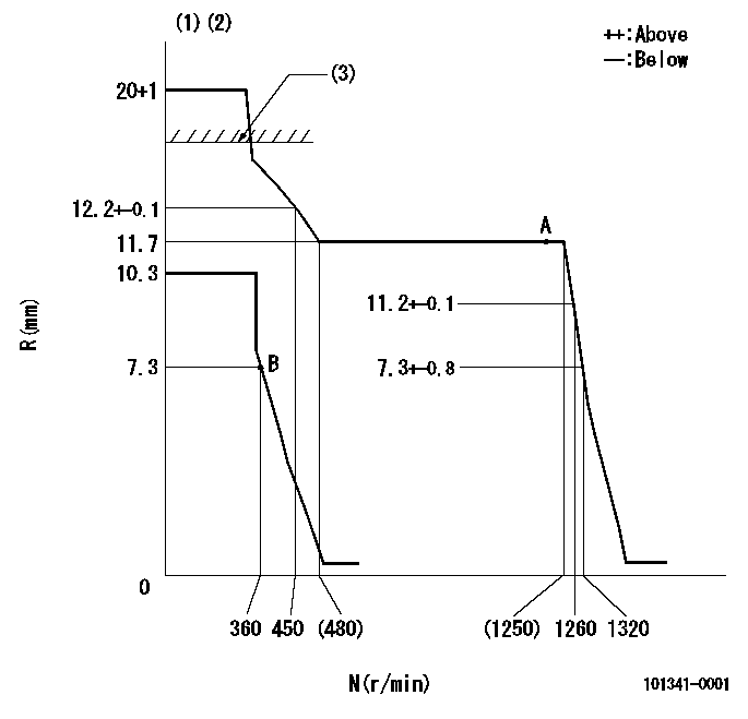
N:Pump speed
R:Rack position (mm)
(1)Target notch: K
(2)Tolerance for racks not indicated: +-0.05mm.
(3)RACK CAP: R1
----------
K=18 R1=(17.5)mm
----------
----------
K=18 R1=(17.5)mm
----------
Speed control lever angle

F:Full speed
I:Idle
(1)Stopper bolt setting
----------
----------
a=(19deg)+-5deg b=(27deg)+-5deg
----------
----------
a=(19deg)+-5deg b=(27deg)+-5deg
Stop lever angle

N:Pump normal
S:Stop the pump.
(1)Normal
----------
----------
a=19deg+-5deg b=53deg+-5deg
----------
----------
a=19deg+-5deg b=53deg+-5deg
Timing setting

(1)Pump vertical direction
(2)Position of gear mark 'Z' at No 1 cylinder's beginning of injection
(3)B.T.D.C.: aa
(4)-
----------
aa=16deg
----------
a=(120deg)
----------
aa=16deg
----------
a=(120deg)
Information:
Introduction
The problem that is identified below does not have a known permanent solution. Until a permanent solution is known, use the solution that is identified below.Problem
If the engine is stored for 6 months or more, the fuel injection pump linkage needs to be lubricated.Solution
Follow the procedure in this article to lubricate the fuel injection pump linkage.
Remove the fuel shutoff solenoid. Refer to Disassembly and Assembly, "Fuel Shutoff Solenoid - Remove and Install" for the correct procedure.
Spray the fuel control rack with a suitable lubricant spray.
Use a suitable magnet to operate the fuel control rack. The operation of the fuel control rack will disperse the lubricant.Note: If the fuel control rack does not move freely, then the fuel injection pump should be replaced. Refer to Disassembly and Assembly, "Fuel Injection Pump - Remove and Install" for the correct procedure.
Install the fuel shutoff solenoid. Refer to Disassembly and Assembly, "Fuel Shutoff Solenoid - Remove and Install" for the correct procedure.
Record the repair in the Service Information Management System (SIMSi), including the engine/machine serial number and the date of the repair.