Information injection-pump assembly
BOSCH
9 400 613 523
9400613523
ZEXEL
101272-3010
1012723010
KOMATSU
6142751205
6142751205

Rating:
Service parts 101272-3010 INJECTION-PUMP ASSEMBLY:
1.
_
5.
AUTOM. ADVANCE MECHANIS
6.
COUPLING PLATE
7.
COUPLING PLATE
8.
_
9.
_
10.
NOZZLE AND HOLDER ASSY
11.
Nozzle and Holder
12.
Open Pre:MPa(Kqf/cm2)
13.
NOZZLE-HOLDER
14.
NOZZLE
15.
NOZZLE SET
Cross reference number
BOSCH
9 400 613 523
9400613523
ZEXEL
101272-3010
1012723010
KOMATSU
6142751205
6142751205
Zexel num
Bosch num
Firm num
Name
101272-3010
9 400 613 523
6142751205 KOMATSU
INJECTION-PUMP ASSEMBLY
2D94 * K
2D94 * K
Calibration Data:
Adjustment conditions
Test oil
1404 Test oil ISO4113 or {SAEJ967d}
1404 Test oil ISO4113 or {SAEJ967d}
Test oil temperature
degC
40
40
45
Nozzle and nozzle holder
105780-8140
Bosch type code
EF8511/9A
Nozzle
105780-0000
Bosch type code
DN12SD12T
Nozzle holder
105780-2080
Bosch type code
EF8511/9
Opening pressure
MPa
17.2
Opening pressure
kgf/cm2
175
Injection pipe
Outer diameter - inner diameter - length (mm) mm 6-2-600
Outer diameter - inner diameter - length (mm) mm 6-2-600
Tester oil delivery pressure
kPa
157
157
157
Tester oil delivery pressure
kgf/cm2
1.6
1.6
1.6
Direction of rotation (viewed from drive side)
Right R
Right R
Injection timing adjustment
Direction of rotation (viewed from drive side)
Right R
Right R
Injection order
1-2
Pre-stroke
mm
2.2
2.15
2.25
Beginning of injection position
Drive side NO.1
Drive side NO.1
Difference between angles 1
Cyl.1-2 deg. 90 89.5 90.5
Cyl.1-2 deg. 90 89.5 90.5
Injection quantity adjustment
Adjusting point
A
Rack position
10.3
Pump speed
r/min
750
750
750
Average injection quantity
mm3/st.
39
38
40
Max. variation between cylinders
%
0
-2
2
Basic
*
Fixing the lever
*
Injection quantity adjustment_02
Adjusting point
B
Rack position
8+-0.5
Pump speed
r/min
400
400
400
Average injection quantity
mm3/st.
8.8
8
9.6
Max. variation between cylinders
%
0
-15
15
Fixing the rack
*
Remarks
Adjust only variation between cylinders; adjust governor according to governor specifications.
Adjust only variation between cylinders; adjust governor according to governor specifications.
Test data Ex:
Governor adjustment

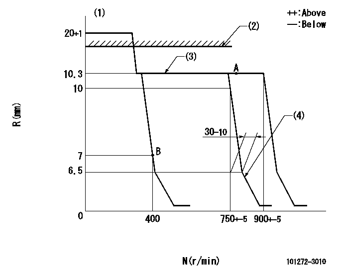
N:Pump speed
R:Rack position (mm)
(1)Target notch: K
(2)RACK CAP: R1
(3)Idle spring not operating.
(4)Idle sub spring setting: L1.
----------
K=12 R1=(18)mm L1=6.5-0.5mm
----------
----------
K=12 R1=(18)mm L1=6.5-0.5mm
----------
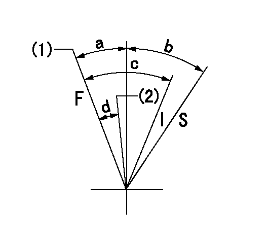
Speed control lever angle

I:Idle
S:Stop
(1)Set the pump speed at aa. ( At delivery )
(2)Pump speed = bb
----------
aa=900r/min bb=750r/min
----------
a=10deg+-5deg b=32deg+-3deg c=24deg+-5deg d=7deg+-5deg
----------
aa=900r/min bb=750r/min
----------
a=10deg+-5deg b=32deg+-3deg c=24deg+-5deg d=7deg+-5deg
Timing setting

(1)Pump vertical direction
(2)Position of camshaft's key groove at No 1 cylinder's beginning of injection
(3)-
(4)-
----------
----------
a=(50deg)
----------
----------
a=(50deg)
Information:
Ensure that all components are free of contaminants before installing. Contaminants may cause premature wear and reduced component service life.
Note: Disposition and Recycling - Common components of exhaust aftertreatment devices include, but are not limited to, cordierite, silicon carbide, iron zeolite, vanadium, platinum, and palladium. After the devices are used in an engine exhaust flow they can include some by-products that result from combustion. Follow applicable Federal, State, and local regulations when handling or discarding used aftertreatment devices
Illustration 1 g03842051
Note: Prior to removal of the catalyst, identify the position of the catalysts and airflow direction. Ensure that the catalyst part number position and the air flow direction remain the same.
Remove Diesel Particulate Filter (DPF) hatch cover (1) nuts, bolts, and washers.
Remove hatch cover (1) from the reactor unit.
Remove gasket assembly from the sealing surface of the hatch cover.
Carefully remove DPF catalyst assembly by removing the V band clamps. If necessary, repeat for other PDF catalysts. Take note of DPF air flow direction and location for reassembly.
Carefully install DPF catalyst into the cabinet with new gaskets. Verify correct position and air flow direction of the DPF.
DPF should always be installed in the direction shown in illustration 1. The long end of the DPF should be installed in the sleeve of the reactor and secured with the proper V band clamps.
For verified applications, replacement DPFs must have the proper tags and meet all documentation requirements.
Apply final torque to V band clamps. Refer to Specifications, SENR3130, "Torque Specifications" for the proper torque.
Replace all inner backing strip gaskets on the DPF catalyst cover.
Install DPF cover assembly.
Replace all damaged bolts.
Apply final torque to all bolts in a circular pattern. Refer to Specifications, SENR3130, "Torque Specifications" for the proper torque.
Verify that all bolts are at the proper torque value.
Have questions with 101272-3010?
Group cross 101272-3010 ZEXEL
Komatsu
101272-3010
9 400 613 523
6142751205
INJECTION-PUMP ASSEMBLY
2D94
2D94