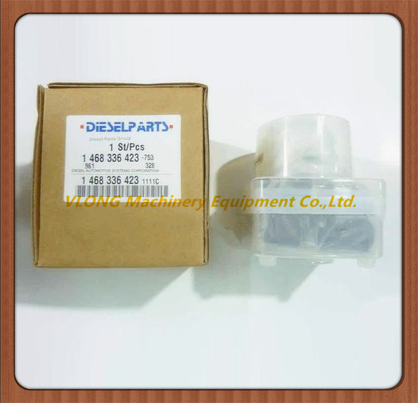
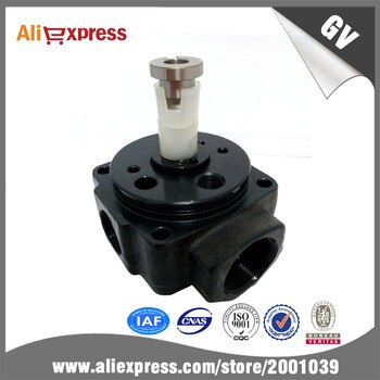
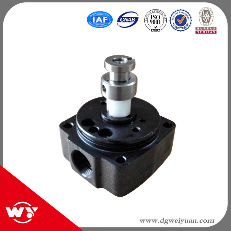
Information hydraulic head
BOSCH
9 461 628 952
9461628952
ZEXEL
146403-6920
1464036920

Rating:
Compare Prices: .
As an associate, we earn commssions on qualifying purchases through the links below

4pcs/lot 4 cyl head rotor 146403-6920 engine car professional durable injection VE rotor head 146403-6920
YUZHUIUS Small volume, large flow and high lift pressure. || Compact structure, convenient maintenance and low operating cost. || Low noise, good reliability, long service life, energy saving and consumption reduction. || Static ring mechanical seal, high pressure resistance, not easy to wear, no leakage. || 4pcs/lot 4 cyl head rotor 146403-6920 engine car professional durable injection VE rotor head 146403-6920
YUZHUIUS Small volume, large flow and high lift pressure. || Compact structure, convenient maintenance and low operating cost. || Low noise, good reliability, long service life, energy saving and consumption reduction. || Static ring mechanical seal, high pressure resistance, not easy to wear, no leakage. || 4pcs/lot 4 cyl head rotor 146403-6920 engine car professional durable injection VE rotor head 146403-6920

$96.95
01 Feb 2024
CN: Diesel Injection Par
1PC Diesel Engine Parts VE Head Rotor 4-Cylinder 146403-6920 1464036920 6920
Generic Manufacturer Part Number:146403-6920 1464036920,Stamping No.6920. || Application: Fits for Diesel Engine. || More Detail:VE Head Rotor 146403-6920,4 Cylinders,Right . || Premium quality: Our Head Rotor Diesel Fuel Injection Pump Parts are made of high-quality materials, ensuring durability and longevity. || Upgrade your diesel engine's performance with the Head Rotor. This high-quality head rotor is the key to unlocking maximum power and efficiency for your vehicle.Whether you're looking for improved fuel efficiency, smoother operation, or enhanced acceleration, this pump rotor head will deliver superior results.
Generic Manufacturer Part Number:146403-6920 1464036920,Stamping No.6920. || Application: Fits for Diesel Engine. || More Detail:VE Head Rotor 146403-6920,4 Cylinders,Right . || Premium quality: Our Head Rotor Diesel Fuel Injection Pump Parts are made of high-quality materials, ensuring durability and longevity. || Upgrade your diesel engine's performance with the Head Rotor. This high-quality head rotor is the key to unlocking maximum power and efficiency for your vehicle.Whether you're looking for improved fuel efficiency, smoother operation, or enhanced acceleration, this pump rotor head will deliver superior results.
You can express buy:
USD 45
18-04-2019
18-04-2019
Diesel Pump Head Rotor 146403-6920 Rotor Head VE4/10R
USD 55.69
01-07-2019
01-07-2019
YK403-6920 146403-6920 for YK VE head rotorheadrotor rotor head
USD 56.25
23-10-2018
23-10-2018
Auto spare part diesel engine part head rotor 146403-6920
Cross reference number
Zexel num
Bosch num
Firm num
Name
146403-6920
9 461 628 952
HYDRAULIC HEAD
C 11FV DISTRIBUTOR HEAD parts(VE) Others
C 11FV DISTRIBUTOR HEAD parts(VE) Others
Information:
Start By:a. remove oil pumpb. remove timing gear coverc. remove flywheel housingd. remove pistons For more detail about removal of main bearings, see the topic "Remove & Install Crankshaft Main Bearings" in this module. 1. Check each bearing cap (1) for its location on the engine. Each cap has an arrow which is toward the front of the block and a number which gives the location of that cap. Keep each bearing with the correct cap.2. Remove bearing caps No. 2 through No. 6. Remove thrust plates from No. 4 upper bearing.3. Install one of the flywheel bolts in each end of the crankshaft. Fasten a hoist to the crankshaft as shown. Remove No. 1 and No. 7 main bearing caps. Remove the crankshaft. Weight of the crankshaft is 181 kg (400 lb).
Be careful not to damage the crankshaft journals when the crankshaft is removed.
4. Remove crankshaft gear (2) with Tooling (A).5. Remove dowel and pin from crankshaft with Tooling (B).Install Crankshaft
1. Install pin (1) in the crankshaft end until it is extended from the surface a distance of 6.4 0.5 mm (.25 .02 in).2. Install dowel (2) until it is extended from the surface a distance of 4.1 0.5 mm (.16 .02 in). 3. Heat crankshaft gear (3) to a maximum temperature of 232°C (450°F). Install gear (3) on the crankshaft with groove (4) in alignment with dowel (2).4. Make sure the upper main bearings are clean. Put clean oil on the upper main bearings and journals of the crankshaft. 5. Install one of the flywheel bolts in each end of the crankshaft. Fasten a hoist to the crankshaft and put it in position in the block.
Use care to prevent damage to the crankshaft journals. Make sure the "V" mark on the crankshaft gear is in alignment with the "V" mark on the idler gear.
For more detail about installation of main bearings, see Remove And Install Crankshaft Main Bearings.6. Check the bearing clearances with Plastigage.7. Put clean engine oil on the bolts for caps No. 1 and No. 7. Install No. 1 and No. 7 caps with the bolts finger tight. Make sure the arrows on the caps are toward the front of the block. 8. Install thrust plates (5) for the No. 4 upper main bearing. Install the thrust plates with the side that has identification "BLOCK SIDE" toward the cylinder block.9. Put clean oil on the bolts for caps No. 2 through No. 6. Install caps No. 2 through No. 6 with the bolts finger tight. Make sure the arrows are toward the front of the block.
Do not use an impact wrench to tighten the bolts the additional 120 degrees.
10. Tighten the cap bolts as follows:a. Tighten the bolts on the tab end of the caps first to a torque of 260 14 N m (190
Have questions with 146403-6920?
Group cross 146403-6920 ZEXEL
146403-6920
9 461 628 952
HYDRAULIC HEAD