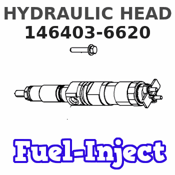
Information hydraulic head
BOSCH
9 461 616 827
9461616827
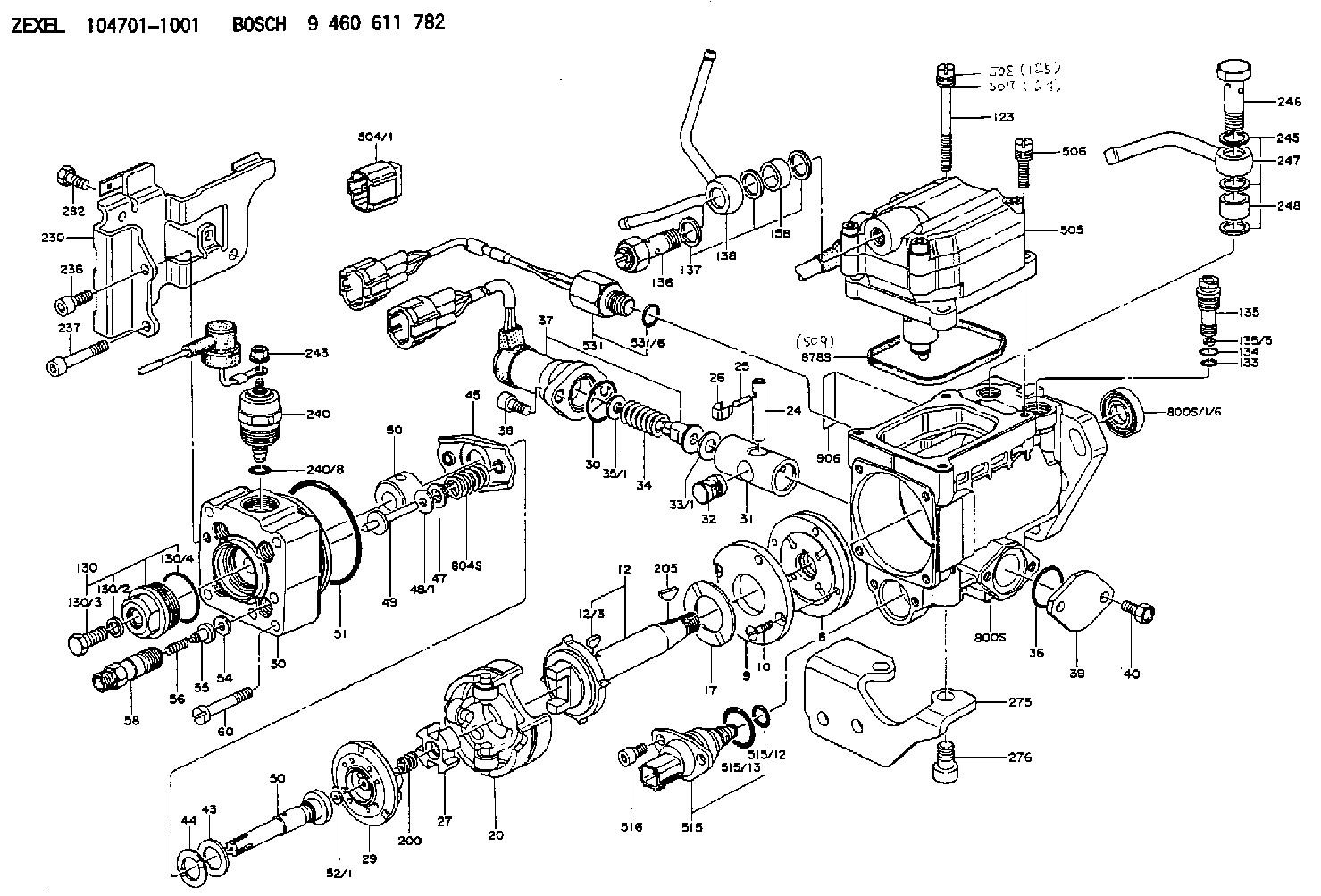
ZEXEL
146403-6620
1464036620
ISUZU
8971328670
8971328670
Rating:
Compare Prices: .
As an associate, we earn commssions on qualifying purchases through the links below

Fuel Injection VE Pump Head Rotor 4/10R 146403-6620 8971328670 for Isuzu Engine 4JG2-TC
FGNTWP Part Number:146403-6620, 1464036620, 8971328670, 9 461 616 827, 9461616827 || Application:for Isuzu Engine 4JG2-TC
FGNTWP Part Number:146403-6620, 1464036620, 8971328670, 9 461 616 827, 9461616827 || Application:for Isuzu Engine 4JG2-TC

Fuel Injection VE Pump Head Rotor 4/10R 146403-6620 8971328670 for Isuzu Engine 4JG2-TC
FGNTWP Part Number:146403-6620, 1464036620, 8971328670, 9 461 616 827, 9461616827
FGNTWP Part Number:146403-6620, 1464036620, 8971328670, 9 461 616 827, 9461616827

Tendparts Fuel Pump Head Rotor 146403-6620 8971328670 Compatible With Isuzu Engine 4JG2T 4JG2-TC
Tendparts Part Numbers: 146403-6620 8971328670 1464036620 9 461 616 827 9461616827 || Compatible With Isuzu Engine 4JG2T 4JG2-TC || Package Includes: 1x Fuel Pump Head Rotor || Easy to Install. Manufactured to Precise OE Requirements for Perfect Fit. Reliable Performance. || Replacement Parts. As Good as OEM at a Fraction of the Price. Exact Same Performance as Original.
Tendparts Part Numbers: 146403-6620 8971328670 1464036620 9 461 616 827 9461616827 || Compatible With Isuzu Engine 4JG2T 4JG2-TC || Package Includes: 1x Fuel Pump Head Rotor || Easy to Install. Manufactured to Precise OE Requirements for Perfect Fit. Reliable Performance. || Replacement Parts. As Good as OEM at a Fraction of the Price. Exact Same Performance as Original.
You can express buy:
USD 45
13-05-2025
13-05-2025
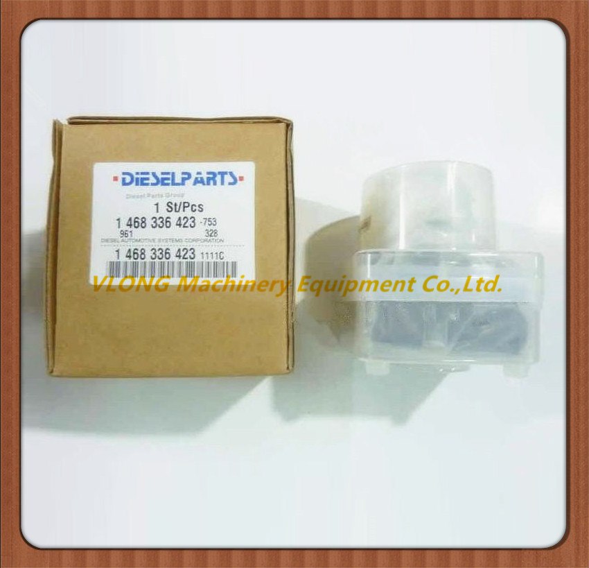
High Quality Diesel VE Pump Head Rotor 146405-7920 146403-9720 146403-6620 096400-1451 146404-2200 4 Cylinder VE Pump Rotor Head

USD 56.25
12-11-2022
12-11-2022
USD 45
18-04-2019
18-04-2019
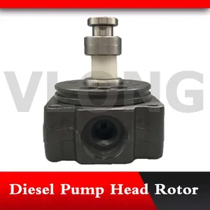
Diesel Pump Head Rotor 146403-6620 Rotor Head VE4/11R for 4JG2-TC
Images:
USD 55.69

[01-Jul-2019]
USD 55.69

[01-Jul-2019]
USD 55.69

[01-Jul-2019]
US $50.00

[23-Dec-2016]
Include in ###:
Cross reference number
Zexel num
Bosch num
Firm num
Name
146403-6620
9 461 616 827
8971328670 ISUZU
HYDRAULIC HEAD
C 11FV DISTRIBUTOR HEAD parts(VE) Others
C 11FV DISTRIBUTOR HEAD parts(VE) Others
Information:
3. Remove bearing caps (1) from the two connecting rods. Put pieces of rubber hose or tape on the threads of the connecting rod bolts as protection for the crankshaft. 4. Push the pistons up until the piston rings are clear of the cylinder liner. Remove pistons (2). Keep each cap with the respective connecting rod.
Do not turn the crankshaft while any of the connecting rods are in the engine without the caps installed. Do not damage the cooling tubes when the pistons are removed.
Install Pistons
1. Put clean engine oil on the piston rings, connecting rod bearings and cylinder liners. 2. Put two pistons in position opposite of each other in the correct bore of the block. install pistons (1) with Tool (A).
Be sure the pistons are installed with flat surfaces (2) of the connecting rods toward each other and the chamfered sides (4) toward the crankshaft.
For more detail about installation of connecting rod bearings, see remove and install connecting rod bearings.3. Check the bearing clearance with Plastigage (B).
Do not use an impact wrench to tighten the nuts the additional 120 degrees.
4. Put clean engine oil on bolts (5). Install caps (3) and nuts finger tight. Tighten each nut to a torque of 80 8 N m (60 6 lb ft). Put a mark across the nuts and bolts. Tighten each nut 120 degrees more.5. Check the side clearance between two connecting rods on the same crankshaft journal. Clearance must be 0.28 to 0.84 mm (.011 to .033 in) for new rods.End By:a. install oil pumpb. install cylinder headsDisassemble & Assemble Pistons
Start By:a. remove pistons 1. Remove bearing halves (2) from the connecting rod and connecting rod cap. New retainer rings allow the use of pliers to remove retainer rings (1).2. Use Tool (C) or pliers to remove retainer rings (1) from each side of the piston. Remove pin (3) and the connecting rod from the piston. 3. Use Tool (A) to remove the piston rings from piston (4). 4. Heat the connecting rod to a temperature of 177° - 204°C (350° - 400°F). Put 5P-8651 Spacer (12) in the base plate. Put connecting rod in position on the base plate of Tooling (B).5. Put the connecting rod piston pin bearing end in the center of the port assembly of Tooling (B). Install pin (8) in the center of the bore for the connecting rod bearings.6. Install 5P-8650 adapter (10). Put the hole in the adapter in alignment with the hole in the base plate of Tooling (B).7. Install clamp bar (11) and clamp pin (7).8. Install new piston pin bearing (6) on adapter (10). The old bearing is pushed out by Tooling (B) as the new bearing is installed.9. Put 5P8649 Adapter (9) in position as shown with the taper side down. The piston pin bearing joint must be in alignment with the hole in adapter (10) and the base plate of Tooling (B).10. Put pusher (5) on adapter (9).11. Use Tooling (B) to push
Have questions with 146403-6620?
Group cross 146403-6620 ZEXEL
Isuzu
146403-6620
9 461 616 827
8971328670
HYDRAULIC HEAD