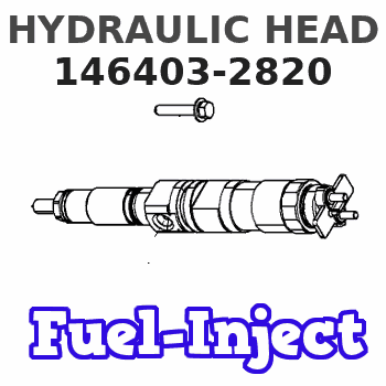
Information hydraulic head
BOSCH
9 461 614 110
9461614110
ZEXEL
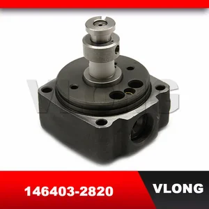
146403-2820
1464032820
MAZDA
PN4013V20
pn4013v20
Rating:
Compare Prices: .
As an associate, we earn commssions on qualifying purchases through the links below

VE Pump Rotor Head 146403-9620 146401-1920 146401-4420 146403-2820 146403-3020 4 Cylinder Diesel VE Pump Head Rotor - (Color: 146403-9620)
Generic Color: 146403-9620
Generic Color: 146403-9620

VE Pump Head Rotor 4/10R 146403-2820 for Isuzu Engine 4JG2 Mazda ED33
FGNTWP Part Number:146403-2820, 1464032820, PN4013V20, 9461614110, 9 461 614 110 || Applications:Fit for Mazda ED33
FGNTWP Part Number:146403-2820, 1464032820, PN4013V20, 9461614110, 9 461 614 110 || Applications:Fit for Mazda ED33

You can express buy:
USD 45
13-05-2025
13-05-2025
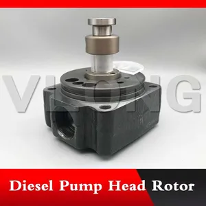
VLONG New High Pressure Fuel Injector Pump Rotor Head VE4/10R 4 Cyl 10MM VE Hydraulic Head 9 461 615 070 9461615070 146403-2820
USD 44.2
13-05-2025
13-05-2025
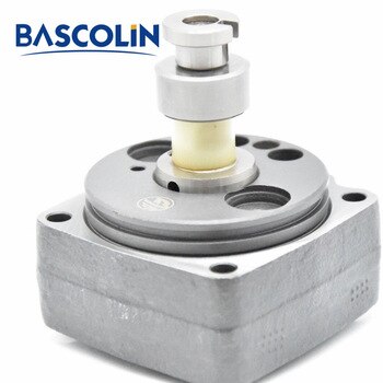
High Quality VE Pump Rotor Head 146403-9620 146401-1920 146401-4420 146403-2820 146403-3020 4 Cylinder Diesel VE Pump Head Rotor
USD 39.5
10-11-2022
10-11-2022
Images:
USD 39.5

[10-Nov-2022]
USD 55.69

[10-Nov-2022]
USD 45

[18-May-2019]
USD 56.25

[21-Jul-2018]
Include in ###:
Cross reference number
Zexel num
Bosch num
Firm num
Name
146403-2820
9 461 614 110
PN4013V20 MAZDA
HYDRAULIC HEAD
C 11FV DISTRIBUTOR HEAD parts(VE) Others
C 11FV DISTRIBUTOR HEAD parts(VE) Others
Information:
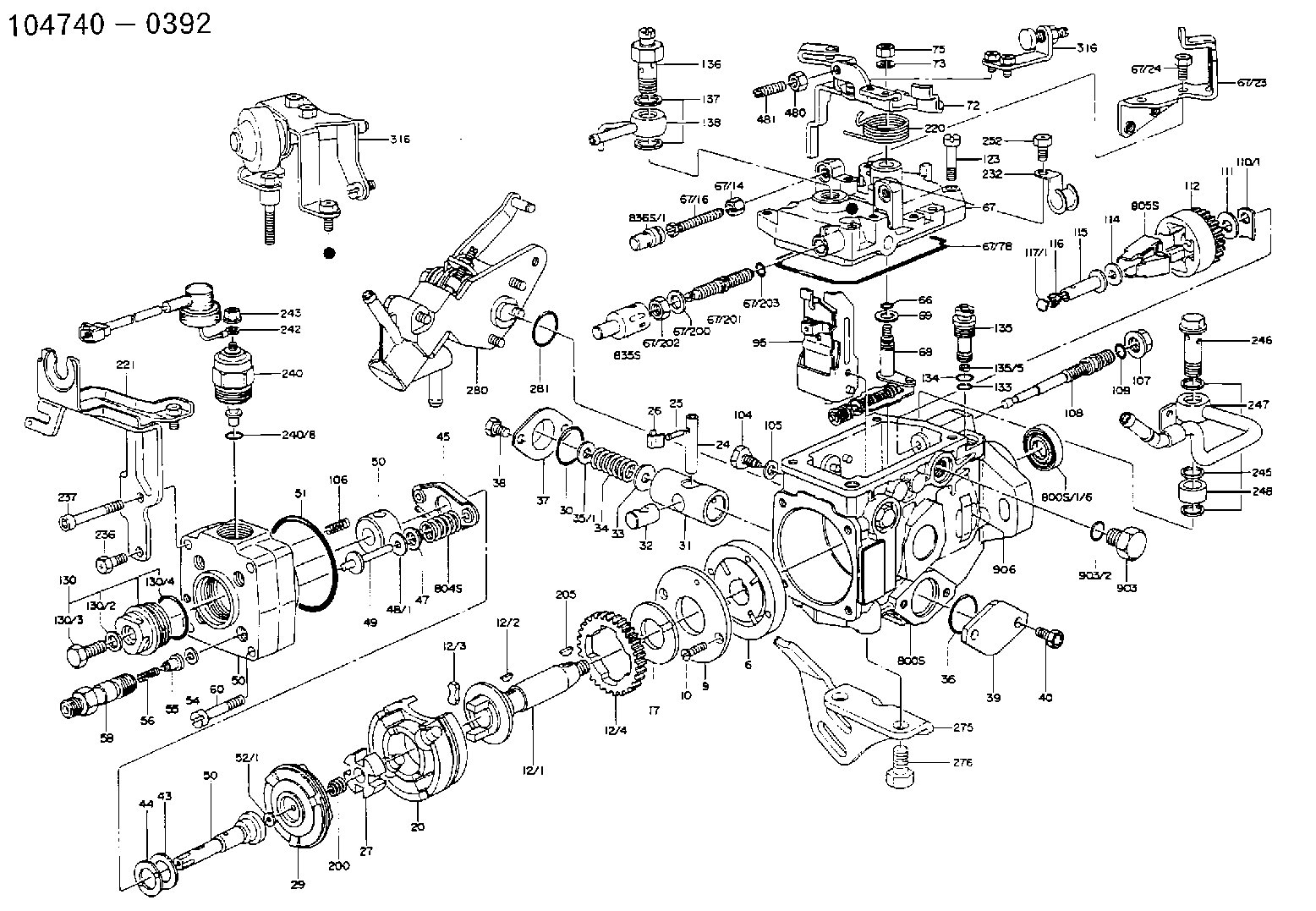
1. Remove tachometer drive (3) from transfer pump cover (4).2. Remove bolts (1). Separate cover (4) and pump body (2). 3. Remove lip-type seal (6) from the cover. Remove plug (5), the seal, spring and plunger (bypass valve) from the cover. 4. Remove nut (10) from shaft (7). Remove gear (9) and key (11).5. Remove shaft (7) and gear (8) as a unit. Remove gear (8) from drive shaft (7) with a press.6. Remove idler gear (12). 7. Remove bushing (14), two lip-type seals and the bottom bearing from pump body (2).8. Remove check valve (13).Assemble Fuel Transfer Pump
1. Install bushing (4) in body (3) with Tooling (B). The bushing must be .80 .50 mm (.031 .020 in) below the (gear) surface of the body.2. Install the check valve in the body with Tooling (A).3. Install lip-type seal (5) with Tooling (C). Install the seal until it is 26.19 .13 mm (1.031 .005 in) from the bottom (drive gear) surface of body (3) and with the lip toward bushing (4) as shown.4. Install lip-type seal (6) with Tooling (D). Install the seal until it is 14.2 0.5 mm (.559 .020 in) from the bottom (drive gear) surface of body (3) and with the lip away from seal (5) as shown.5. Install bearing (7) in body (3) with Tooling (E). The bearing must be even with the bottom (drive gear) surface of the pump body. 6. Heat gear (8) to a maximum temperature of 315° C (600° F). Install gear (8) on shaft (11) until dimension (X) is 49.71 0.25 mm (1.957 .010 in).7. Install the drive shaft and gear in body (3). Install the key, gear (10) and nut (9). Tighten the nut to a torque of 30 7 N m (22 5 lb ft).8. Install idler gear (12) in body (3).9. Install lip-type seal (2) with Tooling (C). Install the seal until it is 22.61 .05 mm (.890 .002 in) from the top surface of cover (1) with the lip toward the inside as shown. 10. Install plunger (14) (bypass valve), spring (15) and seal and plug (13) in pump cover (1). Tighten plug (13) to a torque of 37 4 N m (27 3 lb ft).
Do not let the liquid gasket enter the pump during application or assembly.
11. Put 7M-7260 Liquid Gasket Material on the surface of cover (1). Install cover (1) on pump body (3). The drive shaft must turn freely after the bolts that hold the transfer pump together are tightened.12. Install the tachometer drive on cover (1).End By:a. install fuel transfer pump
Have questions with 146403-2820?
Group cross 146403-2820 ZEXEL
Mazda
146403-2820
9 461 614 110
PN4013V20
HYDRAULIC HEAD