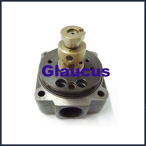
Information hydraulic head
BOSCH
9 461 615 070
9461615070
ZEXEL
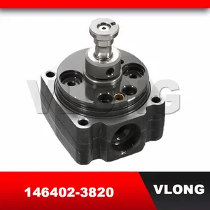
146402-3820
1464023820
ISUZU
8970321660
8970321660

Rating:
Compare Prices: .
As an associate, we earn commssions on qualifying purchases through the links below

VE Pump Head Rotor 4/11L 146402-3820 8970321660 for Isuzu Engine 4JA1
FGNTWP Part Number:146402-3820, 1464023820, 9 461 615 070, 9461615070, 8970321660 || Application:Fit for Engine: Isuzu 4JA1
FGNTWP Part Number:146402-3820, 1464023820, 9 461 615 070, 9461615070, 8970321660 || Application:Fit for Engine: Isuzu 4JA1

VE Pump Head Rotor 4/11L 146402-3820 8970321660 for Isuzu Engine 4JA1
ADPelcote Part number:146402-3820 || Applications:for Isuzu Engine 4JA1
ADPelcote Part number:146402-3820 || Applications:for Isuzu Engine 4JA1

You can express buy:
USD 43
13-05-2025
13-05-2025
4JA1 engine fuel injector Diesel VE pump rotor head for ISUZU Campo Trooper 2499CC 2.5L 146402-3820 146402 3820 1464023820
USD 45
13-05-2025
13-05-2025
VLONG High Pressure Fuel Injector Pump Rotor Head VE4/11L VE Hydraulic Head Rotor For ISUZU Pickup 4JA1 104641-6990 146402-3820
USD 45
13-05-2025
13-05-2025
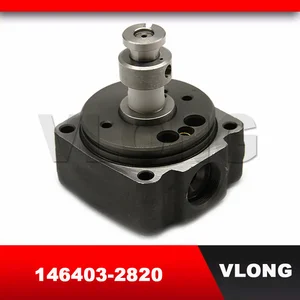
VLONG New High Pressure Fuel Injector Pump Rotor Head VE4/10R 4 Cyl 10MM VE Hydraulic Head 9 461 615 070 9461615070 146403-2820
Images:
USD 131.81

[31-Aug-2022]
USD 56.25

[23-Oct-2018]
USD 45

[18-Apr-2019]
Include in ###:
Cross reference number
Zexel num
Bosch num
Firm num
Name
146402-3820
9 461 615 070
8970321660 ISUZU
HYDRAULIC HEAD
C 11FV DISTRIBUTOR HEAD parts(VE) Others
C 11FV DISTRIBUTOR HEAD parts(VE) Others
Information:
1. Drain the coolant from the cooling system to a level below that of the water pump.2. Remove elbow (1).3. Remove bolts (4) that hold cover (2) to the water pump. Remove bolts (5) that hold elbow (3) to cover (2).4. Remove line (6).5. Remove cover (2). Remove elbow (3). 6. Remove four bolts (7).7. Remove nuts (8) and one bolt (not shown). Remove water pump.Install Water Pump
1. Put the water pump in position on the timing gear cover. Install nuts (8) and one bolt that hold the pump to the timing gear cover.2. Install four bolts (7). 3. Put clean engine oil or glycerin on O-ring seals (9). Install elbow (3). 4. Put cover (2) in position on the water pump. Install bolts (4) that hold the cover to the water pump and bolts (5) that hold elbow (3) to the cover.5. Install elbow (1).6. Install line (6).7. Fill the cooling system to the proper level. See the Operation & Maintenance Manual.Disassemble Water Pump
Start By:a. remove water pump 1. Remove O-ring seal (1) from adapter (2).2. Remove adapter (2) with a screwdriver. Remove the seal from the edge of adapter (2).3. Remove bolt (3) and washer. 4. Remove impeller (4) from the water pump housing with Tooling (A). 5. Remove seal assembly (5). Remove ring and seal (6). 6. Remove the bolt and washer that hold gear (7) on the water pump shaft.7. Remove gear (7) with Tooling (B).8. Remove bolts and retainer (9).9. Remove O-ring seal (8). 10. Remove shaft (10) and bearings as a unit.11. Remove bearing (11), spacer (12) and bearing (13) from shaft (10).12. Remove lip-type seal from the gear side of the water pump. Remove ring and seal from the impeller side of the water pump.Assemble Water Pump
1. Put clean engine oil or glycerin on the lip of seal (1). Install seal (1) as shown with Tooling (A). 2. Install bearing (4), spacer (3) and bearing (5) on shaft (2). Install shaft (2) in the pump housing. 3. Install retainer (7) and O-ring seal (8).4. Install gear (6). Install washer and bolt that hold gear (6) to shaft (2).
Clean water only is permitted for use as a lubricant for assistance at installation. Do not damage or put hands on the wear surface of the carbon ring or the ceramic ring. Install the ceramic ring with the smoothest face of the ring toward the carbon seal assembly.
5. Put ceramic ring (10) in position in the rubber seal (9). Use hand pressure and Tool (11) (which is with the replacement ring) to install the ceramic ring in the housing. 6. Remove the spring from seal assembly (12). Use hand pressure and Tool (11) (which is with the replacement ring) to install the seal assembly. Push seal assembly on the shaft until the seal faces make light contact. 7. Install spring (13) on the seal assembly and impeller (14) on the shaft. Install the bolt and washer on the shaft. Tighten the bolt to a
Have questions with 146402-3820?
Group cross 146402-3820 ZEXEL
Isuzu
146402-3820
9 461 615 070
8970321660
HYDRAULIC HEAD