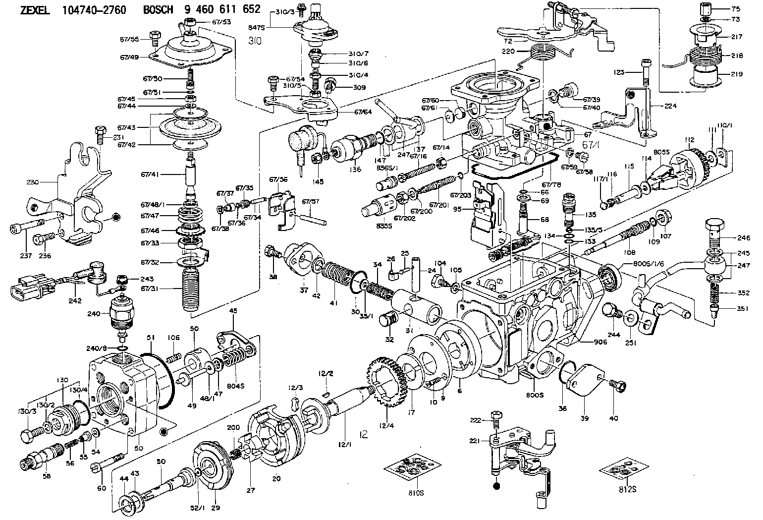
Information hydraulic head
BOSCH
9 461 616 826
9461616826
ZEXEL
146401-4120
1464014120

Rating:
Compare Prices: .
As an associate, we earn commssions on qualifying purchases through the links below

$177.65
23 Aug 2024
CN: Tenlioshun
Tenlioshun New Diesel Fuel Pump Head Rotor VE Pump 146401-4120 Compatible with Nissan
Tenlioshun Part Name: Fuel Pump Head || Part number: 146401-4120 || Compatible with Nissan || Package included: 1 Pieces Fuel Pump Head || Note: Avoid unnecessary returns. Before purchase, please carefully check whether the product model you want to buy matches us. If you don't know, please contact us.
Tenlioshun Part Name: Fuel Pump Head || Part number: 146401-4120 || Compatible with Nissan || Package included: 1 Pieces Fuel Pump Head || Note: Avoid unnecessary returns. Before purchase, please carefully check whether the product model you want to buy matches us. If you don't know, please contact us.
$187.00
26 Aug 2023
CN: Huaxiaoshuai
dertgmlm New Diesel Fuel Pump Head Rotor VE Pump 146401-4120 Fits for Nissan
dertgmlm Part Name: Fuel Pump Head || Part number: 146401-4120 || Fits for Nissan || Package included: 1 Pieces Fuel Pump Head || Note: Avoid unnecessary returns. Before purchase, please carefully check whether the product model you want to buy matches us. If you don't know, please contact us.
dertgmlm Part Name: Fuel Pump Head || Part number: 146401-4120 || Fits for Nissan || Package included: 1 Pieces Fuel Pump Head || Note: Avoid unnecessary returns. Before purchase, please carefully check whether the product model you want to buy matches us. If you don't know, please contact us.
Include in ###:
Cross reference number
Zexel num
Bosch num
Firm num
Name
146401-4120
9 461 616 826
HYDRAULIC HEAD
C 11FV DISTRIBUTOR HEAD parts(VE) Others
C 11FV DISTRIBUTOR HEAD parts(VE) Others
Information:
1. Remove bolts (1) and the washers that hold rocker shaft assembly (2) in position.2. Remove rocker shaft assembly (2). Remove the O-ring seal from the rear rocker arm support bracket.3. Put identification marks on push rods (3) as to their location in the engine. Remove the push rods.Install Rocker Shaft Assembly & Push Rods
1. Install push rods (1). Make sure they are in their original location in the engine and in position in the valve lifters.
Loosen the adjusting screws on the rocker arms. This will prevent a bent valve or push rod during installation of the rocker shaft assembly.
2. Install a new O-ring seal in the rear rocker arm support bracket. Put 2P2506 Thread Lubricant on all of the bolts that hold the rocker shaft assembly in position except for the bolt that goes through the rear rocker arm support bracket.3. Put rocker shaft assembly (2) in position on the engine. Make sure the dowels in the support bracket are in alignment with the dowel holes in the cylinder head. Make sure the rocker arms are engaged with the push rods.4. Install the bolts and washers that hold the rocker shaft assembly in position. Tighten them until they are finger tight.
3304 Engine Sequence
3306 Engine Sequence5. Tighten the bolts that hold the rocker shaft as follows:a. Tighten the bolts in number sequence to a torque of 156 N m (115 lb ft).b. Tighten the bolts in number sequence to a torque of 250 17 N m (185 13 lb ft).c. Tighten the bolts again in number sequence to a torque of 250 17 N m (185 13 lb ft).6. See "Valve Clearance Setting" in Testing & Adjusting. Make an adjustment to the valves so the intake valves have 0.38 mm (.015 in) clearance and the exhaust valves have 0.64 mm (.025 in) clearance. Tighten the locknuts for the adjusting screws to a torque of 29 7 N m (21 5 lb ft).End By:a. install valve cover
Have questions with 146401-4120?
Group cross 146401-4120 ZEXEL
146401-4120
9 461 616 826
HYDRAULIC HEAD