Information hydraulic head
BOSCH
9 461 614 180
9461614180
ZEXEL
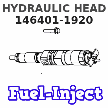
146401-1920
1464011920
ISUZU
8943286040
8943286040
Rating:
Compare Prices: .
As an associate, we earn commssions on qualifying purchases through the links below

VE Pump Rotor Head 146403-9620 146401-1920 146401-4420 146403-2820 146403-3020 4 Cylinder Diesel VE Pump Head Rotor - (Color: 146403-9620)
Generic Color: 146403-9620
Generic Color: 146403-9620

YANNAL PART 1 PC VE Diesel Pump Head Rotor 146401-1920 Suitable for Isuzu Engine Part C240
YANNAL PART Product Name: VE Diesel Pump Head Rotor || Product Name: 146401-1920 || Application: Compatible for Isuzu C240 || Warranty: 1 Year || Note: Please verify your part number before ordering, any problem please feel free to contact us, thanks.
YANNAL PART Product Name: VE Diesel Pump Head Rotor || Product Name: 146401-1920 || Application: Compatible for Isuzu C240 || Warranty: 1 Year || Note: Please verify your part number before ordering, any problem please feel free to contact us, thanks.

VE Diesel Pump Head Rotor 146401-1920 4/9L for Isuzu C240 4 Cylinders Rotor Head
JDPART Product Name: Pump Head Rotor || Higher-quality: Using high-quality materials and manufacturing processes to ensure its reliability, durability and consistent performance. || Application: For Isuzu C240 || Warranty: 1 Year || Note: Please verify your part number before ordering, any problem please feel free to contact us, thanks.
JDPART Product Name: Pump Head Rotor || Higher-quality: Using high-quality materials and manufacturing processes to ensure its reliability, durability and consistent performance. || Application: For Isuzu C240 || Warranty: 1 Year || Note: Please verify your part number before ordering, any problem please feel free to contact us, thanks.
You can express buy:
USD 99.68
13-05-2025
13-05-2025
VE Diesel Pump Head Rotor 146401-1920 4/9L for Isuzu C240 4 Cylinders Rotor Head
USD 44.2
13-05-2025
13-05-2025
High Quality VE Pump Rotor Head 146403-9620 146401-1920 146401-4420 146403-2820 146403-3020 4 Cylinder Diesel VE Pump Head Rotor

USD 46.5
13-05-2025
13-05-2025
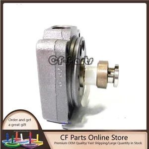
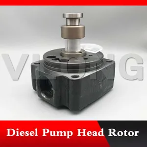
Pump head, rotor head 146401-1920, 9461614180, VE head rotor, 4 cylinders / 9mm Left, without spring,for Engine Injection System
Images:
USD 46.5

[13-May-2025]
USD 169.63

[28-Apr-2025]
USD 79

[10-Nov-2022]
USD 45

[18-Apr-2019]
Include in ###:
Cross reference number
Zexel num
Bosch num
Firm num
Name
146401-1920
9 461 614 180
8943286040 ISUZU
HYDRAULIC HEAD
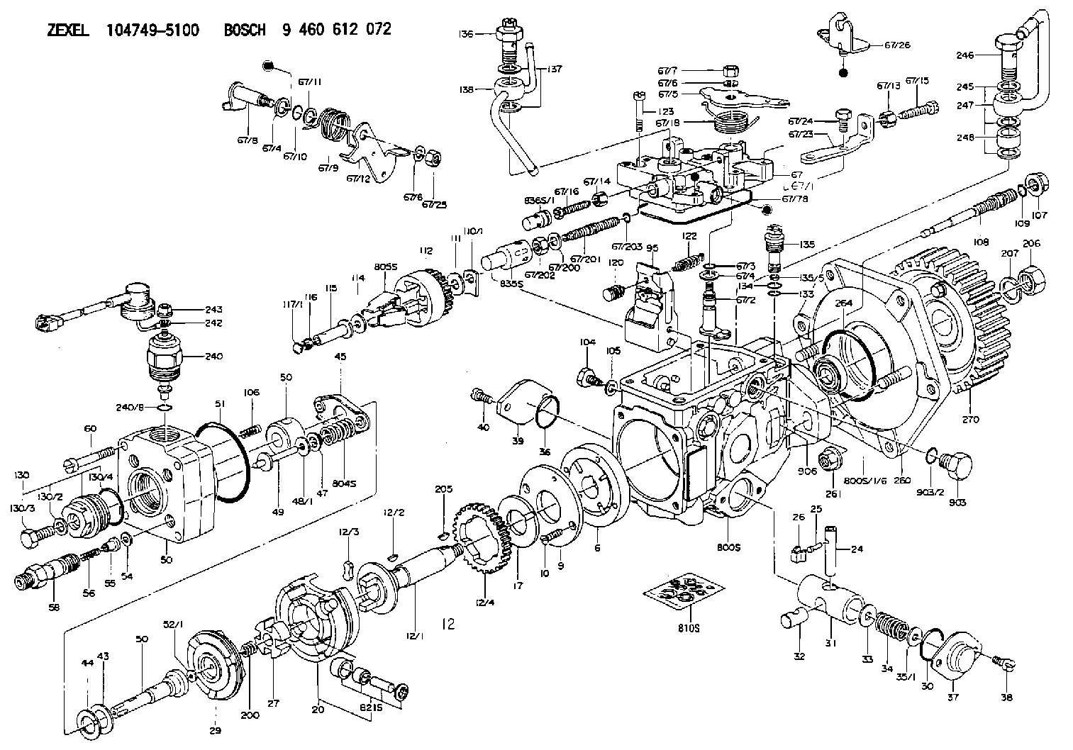
C 11FV DISTRIBUTOR HEAD parts(VE) Others
C 11FV DISTRIBUTOR HEAD parts(VE) Others
Information:
1. Disconnect air line (1) from the fuel ratio control.2. Remove wire seal (4) from the bolts.3. Remove bolts (3) that hold fuel ratio control (2).4. Remove the fuel ratio control by pulling down and out from the collar. The following steps are for the installation of the fuel ratio control.5. Put fuel ratio control (2) in position on the governor. Make sure the valve head of the fuel ratio control is connected in the groove of the collar.6. Install bolts (3) that hold the fuel ratio control to the governor. Connect air line (1) to the fuel ratio control.7. To make an adjustment to the fuel ratio control, see the topic "Governor Adjustment For The Air Fuel Ratio Control" in, Testing & Adjusting Manual SENR6471.8. Install wire seal (4) on the bolts with Tool (A).Disassemble & Assemble Fuel Ratio Control
Start By:a. remove fuel ratio control 1. Put Tool (A) in a vise so that the station being used is not over the vise jaw. Place the fuel ratio control over the pins in Tool (A). Remove bolts (3) and remove cover (26) and gasket (24).
There is spring force behind cover (7). Hold cover (7) in position, and slowly remove the bolts that hold it to release the spring force.
2. Remove bolts (6). Remove cover (7) from housing (10).3. Remove nut (5) and stop (4) from cover (7).4. Remove spring (8), washer (9) and diaphragm (21) from retainer (25). Remove retainer (25) from housing (10).5. Remove tube (1) from the end of extension (19). Remove nut (2) from extension (19) and remove the extension from retainer (25). Remove valve (16), spring (22) and O-ring seal (23) from the extension.6. Remove spring (20), retainer (18) and spring (17) from housing (10).7. Remove piston (12) and valve assembly (14) from the housing.8. Use Tool (B) and remove snap ring (13) and washer (15) from the valve assembly. Remove piston (12) from the valve assembly.9. Remove seal (11) from piston (12).10. If necessary, remove the stem portion from valve assembly (14).11. Clean and inspect all parts. Make a replacement of all parts that are worn and damaged. The following steps are for the assembly of the fuel ratio control.12. If removed during disassembly, assemble the stem portion of valve assembly (14) on the valve using 9S3265 Retaining Compound.13. Lubricate seal (11) lightly with the lubricant being sealed. Put seal (11) on piston (12) and put piston (12) on valve assembly (14).14. Put washer (15) in position on the valve assembly and use Tool (B) to install snap ring (13) on the valve assembly.15. Place housing (10) on Tool (A), and put Tool (C) into the bore of the housing. Lubricate Tool (C) with clean engine oil.16. Push piston (12) into position with a smooth swift motion. Remove Tool (C) from the housing. Place spring (17), retainer (18) and spring (20) in housing (10).17. Put O-ring seal (23) on extension (19). Put spring (22) and valve (16) in position on the
Have questions with 146401-1920?
Group cross 146401-1920 ZEXEL
Isuzu
146401-1920
9 461 614 180
8943286040
HYDRAULIC HEAD