Information hydraulic head
BOSCH
9 461 613 575
9461613575
ZEXEL
146400-5820
1464005820
ISUZU
8941695050
8941695050

Rating:
Compare Prices: .
As an associate, we earn commssions on qualifying purchases through the links below

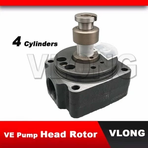
Fuel Injection VE Pump Head Rotor 4/10L 146400-5820 Fit Intended For Engine
Generic spare parts || autoparts || machinery parts || engine parts
Generic spare parts || autoparts || machinery parts || engine parts

$104.69
03 Mar 2022
3.74[1.68] Pounds
CN: china lutong part pl
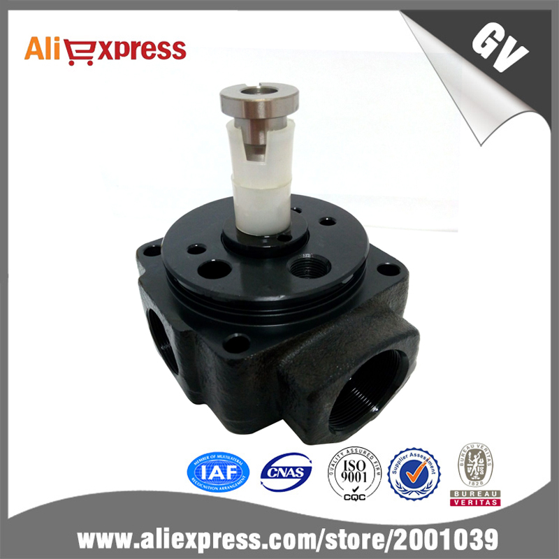
146400-5820 Fuel Injection VE Pump Head Rotor 1464005820 4/10L fits ISUZU Hydraulic Head
DICSCL PARCS 146400-5820 Fuel Injection VE Pump Head Rotor 1464005820 4/10L fits ISUZU Hydraulic Head || Material: Made of high quality for longer durability and strength.100% quality inspection to ensure the high quality. Upgraded packaging to avoid damage. || Easy Installation:No further modification to direct replacement. || OEM Part Number:146400-5820/1464005820 || Estimated Time of Delivery from China: 5-10 working days.Customer satisfaction is always our top priority, we are standing by ready to provide you with reliable assistance with any questions you may have
DICSCL PARCS 146400-5820 Fuel Injection VE Pump Head Rotor 1464005820 4/10L fits ISUZU Hydraulic Head || Material: Made of high quality for longer durability and strength.100% quality inspection to ensure the high quality. Upgraded packaging to avoid damage. || Easy Installation:No further modification to direct replacement. || OEM Part Number:146400-5820/1464005820 || Estimated Time of Delivery from China: 5-10 working days.Customer satisfaction is always our top priority, we are standing by ready to provide you with reliable assistance with any questions you may have

$104.69
14 May 2022
3.74[1.68] Pounds
CN: china lutong part pl
Fuel Injection VE Pump Head Rotor 146400-5820 4/10L fits ISUZU Hydraulic Head Diesel Engine
DICSCL PARCS Material:High quality,durable and resistant to damage. || Easy to installation || Fuel Injection VE Pump Head Rotor 146400-5820 4/10L fits Diesel Engine || Replace OEM:146400-5820 || Estimated Time of Delivery from China: 5-10 working days.
DICSCL PARCS Material:High quality,durable and resistant to damage. || Easy to installation || Fuel Injection VE Pump Head Rotor 146400-5820 4/10L fits Diesel Engine || Replace OEM:146400-5820 || Estimated Time of Delivery from China: 5-10 working days.
You can express buy:
USD 44.3
13-05-2025
13-05-2025
High Quality VE Pump Rotor Head 146401-0820 146400-9720 146400-5820 146401-4920 146402-0820 4 Cylinder Diesel VE Pump Head Rotor
USD 55.69
25-05-2019
25-05-2019
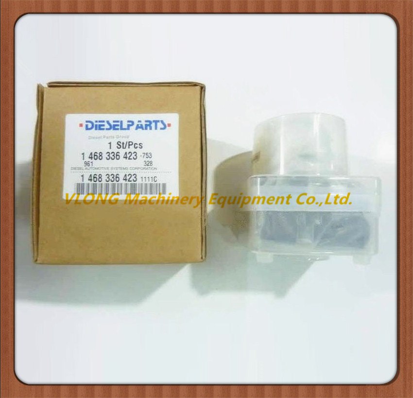
146400-5820 for YK VE head rotor/headrotor/ rotor head
USD 45
18-04-2019
18-04-2019
Diesel Pump Head Rotor 146400-5820 Rotor Head VE4/10L
Images:
USD 55.69

[01-Jul-2019]
USD 56.25

[12-Nov-2022]
Include in ###:
Cross reference number
Zexel num
Bosch num
Firm num
Name
146400-5820
9 461 613 575
8941695050 ISUZU
HYDRAULIC HEAD
C 11FV DISTRIBUTOR HEAD parts(VE) Others
C 11FV DISTRIBUTOR HEAD parts(VE) Others
Information:
Alternator (Bosch)
The alternator is driven by V-belts from the crankshaft pulley. This alternator is a three phase, self-rectifying charging unit. The regulator is part of the alternator.
Bosch Alternator
(1) Fan. (2) Stator winding. (3) Field winding. (4) Regulator. (5) Ball bearing. (6) Roller bearing. (7) Rotor. (8) Rectifier assembly.This alternator design has no need for slip rings or brushes, and the only part that has movement is the rotor assembly. All conductors that carry current are stationary. The conductors are: the field winding, stator windings, six rectifying diodes, and the regulator circuit components.The rotor assembly has many magnetic poles like fingers with air space between each opposite pole. The poles have residual magnetism (like permanent magnets) that produce a small amount of magnet-like lines of force (magnetic field) between the poles. As the rotor assembly begins to turn between the field winding and the stator windings, a small amount of alternating current (AC) is produced in the stator windings from the small magnetic lines of force made by the residual magnetism of the poles. This AC current is changed to direct current (DC) when it passes through the diodes of the rectifier bridge. Most of this current goes to charge the battery and to supply the low amperage circuit, and the remainder is sent to the field windings. The DC current flow through the field windings (wires around an iron core) now increases the strength of the magnetic lines of force. These stronger lines of force now increase the amount of AC current produced in the stator windings. The increased speed of the rotor assembly also increases the current and voltage output of the alternator.The voltage regulator is a solid state (transistor, stationary parts) electronic switch. It feels the voltage in the system and switches on and off many times a second to control the field current (DC current to the field windings) for the alternator to make the needed voltage output.Alternator (Nippondenso)
The alternator is driven by V-belts from the crankshaft pulley. The Nippondenso alternator has three-phase, full-wave rectified output. It is brushless. The rotor and bearings are the only moving parts. The regulator is part of the alternator.
Nippondenso Alternator
(1) Fan. (2) Front frame assembly. (3) Stator assembly. (4) Rotor assembly. (5) Field winding (coil assembly). (6) Regulator assembly. (7) Condenser (suppression capacitor). (8) Rectifier assembly. (9) Rear frame assembly.When the engine is started and the rotor turns inside the stator windings, three-phase alternating current (AC) and rapidly rising voltage is generated.A small amount of alternating current (AC) is changed (rectified) to pulsating direct current (DC) by the exciter diodes on the rectifier assembly. Output current from these diodes adds to the initial current which flows through the rotor field windings from residual magnetism. This will make the rotor a stronger magnet and cause the alternator to become activated automatically. As rotor speed, current and voltages increase, the rotor field current increases enough until the alternator becomes fully activated.The main battery charging current is charged (rectified) from AC to
Have questions with 146400-5820?
Group cross 146400-5820 ZEXEL
Isuzu
146400-5820
9 461 613 575
8941695050
HYDRAULIC HEAD