Information hydraulic head
BOSCH
9 461 611 682
9461611682
ZEXEL
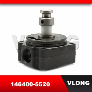
146400-5520
1464005520
ISUZU
8941501530
8941501530

Rating:
Compare Prices: .
As an associate, we earn commssions on qualifying purchases through the links below

You can express buy:

USD 44.8
13-05-2025
13-05-2025
New Diesel Fuel Pump Rotor Head 4Cylinders Diesel VE Pump Head Rotor 146402-3420 146400-2700 146401-0520 146400-8821 146400-5520
USD 45
13-05-2025
13-05-2025
VLONG High Pressure Fuel Injector Pump Rotor Head VE4/9R 4/9R 4 Cyl 9MM Diesel VE Hydraulic Head Rotor 1464005520 146400-5520

USD 44.8
10-11-2022
10-11-2022
Images:
USD 45

[18-Apr-2019]
Cross reference number
Zexel num
Bosch num
Firm num
Name
Information:
(1) Crossbar (from 8B7548 Puller).(2) Spacer plate.(3) S1589 Bolt with two 1S379 Washers.(4) 1D4595 Bolt.(5) 3H465 Plate.(6) 1P2403 Dial Indicator.(7) 1P2394 Adapter Plate.(8) 1P2402 Gauge Body.Make reference to Cylinder Liner Projection in Testing and Adjusting for the complete procedure.1. Install gasket and spacer plate (2) with bolts (3) and two 1S379 Washers. Tighten bolts (3) evenly in four steps: 1st step ... 14 N m (10 lb ft)2nd step ... 35 N m (25 lb ft)3rd step ... 70 N m (50 lb ft)4th step ... 95 N m (70 lb ft)2. Install tools as shown. Tighten bolts (4) evenly in four steps: 1st step ... 7 N m (5 lb ft)2nd step ... 20 N m (15 lb ft)3rd step ... 35 N m (25 lb ft)4th step ... 70 N m (50 lb ft)3. Measure cylinder liner projection with dial indicator (6) in 1P2402 Gauge Body (8) as shown. Measure at four places around each cylinder liner near the clamped area. Cylinder liner projection measurements for any cylinder liner must be ... 0.033 to 0.175 mm (.0013 to .0069 in)Maximum permissible difference between all four measurements ... 0.05 mm (.002 in)Maximum permissible difference between average projection of any two cylinder liners next to each other ... 0.05 mm (.002 in)Maximum permissible difference between average projection of all cylinder liners under one cylinder head ... 0.10 mm (.004 in) If liner projection is not correct, turn the liner to a new position within the bore. If projection can not be corrected this way, move the liner to a different bore. If the projection can not be corrected this way, make reference to Special Instruction, Form No. FMO55228 for complete instructions on the use of 8S3140 Counterboring Tool Arrangement. 4. Minimum permissible depth to machine counterbore to adjust cylinder liner projection ... 0.76 mm (.030 in) Maximum permissible depth to machine counterbore to adjust cylinder liner projection ... 1.14 mm (.045 in)Install a 0.76 mm (.030 in) shim plus any added shims necessary to get the correct cylinder liner projection. Be sure that the 0.76 mm (.030 in) shim is directly under the cylinder liner flange.