Information hydraulic head
BOSCH
9 461 610 704
9461610704
ZEXEL
146400-5020
1464005020
Rating:
Compare Prices: .
As an associate, we earn commssions on qualifying purchases through the links below

$149.15
05 Aug 2024
CN: Tenlioshun
Tenlioshun New Diesel Fuel Pump Head Rotor VE Pump 146400-5020 104640-3050 Compatible with Nissan
Tenlioshun Part Name: Fuel Pump Head || Part number: 146400-5020 104640-3050 || Compatible with Nissan || Package included: 1 Pieces Fuel Pump Head || Note: Avoid unnecessary returns. Before purchase, please carefully check whether the product model you want to buy matches us. If you don't know, please contact us.
Tenlioshun Part Name: Fuel Pump Head || Part number: 146400-5020 104640-3050 || Compatible with Nissan || Package included: 1 Pieces Fuel Pump Head || Note: Avoid unnecessary returns. Before purchase, please carefully check whether the product model you want to buy matches us. If you don't know, please contact us.
$157.00
16 Oct 2023
CN: Huaxiaoshuai
dertgmlm New Diesel Fuel Pump Head Rotor VE Pump 146400-5020 104640-3050 Fits for Nissan
dertgmlm Part Name: Fuel Pump Head || Part number: 146400-5020 104640-3050 || Fits for Nissan || Package included: 1 Pieces Fuel Pump Head || Note: Avoid unnecessary returns. Before purchase, please carefully check whether the product model you want to buy matches us. If you don't know, please contact us.
dertgmlm Part Name: Fuel Pump Head || Part number: 146400-5020 104640-3050 || Fits for Nissan || Package included: 1 Pieces Fuel Pump Head || Note: Avoid unnecessary returns. Before purchase, please carefully check whether the product model you want to buy matches us. If you don't know, please contact us.
Include in ###:
Cross reference number
Zexel num
Bosch num
Firm num
Name
146400-5020
9 461 610 704
HYDRAULIC HEAD
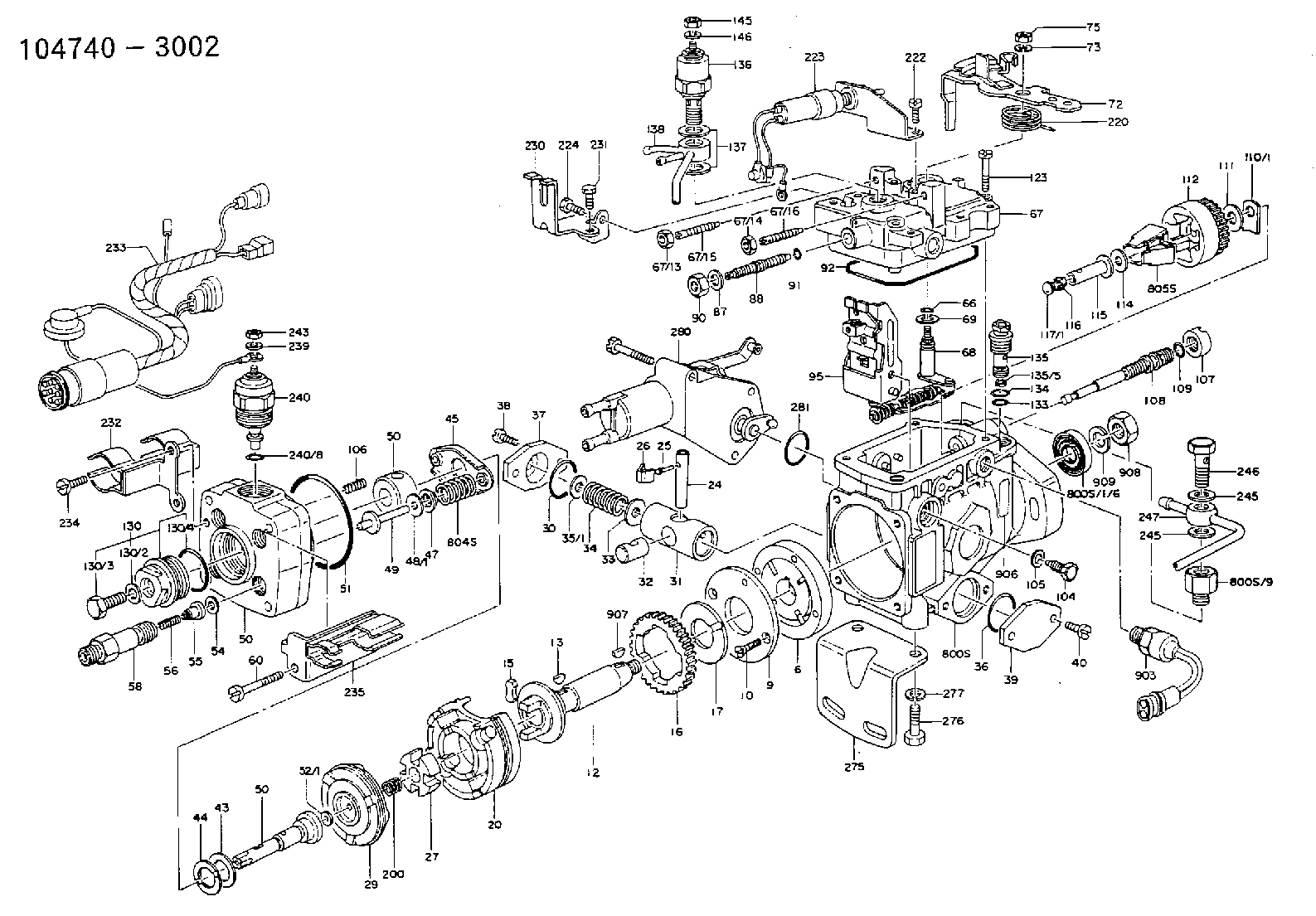
C 11FV DISTRIBUTOR HEAD parts(VE) Others
C 11FV DISTRIBUTOR HEAD parts(VE) Others
Information:
Tighten locknuts (A) on rod ends to ... 12 4 N m (9 3 lb ft)With governor at High Idle, install lever (B) on governor shaft at an angle from vertical of ... 20 5°Dimension (C) approximately ... 438.0 mm (17.25 in)Dimension (D) approximately ... 597.0 mm (23.50 in)Dimension (E) approximately ... 610.0 mm (24.00 in)Dimension (F) approximately ... 100.00 mm (3.94 in)Dimension (G) ... 1.5 mm (.06 in)Adjust bolt (H) to get dimension (F) with engine at High IdleAdjust setscrew (J) so that engine speed is 985 50 rpm with decelerator pedal depressed. Check High Idle speed after adjustment.After linkage has been adjusted, move control lever to High Idle and adjust setscrew (K) to get dimension (G).D7G With Direct Drive Transmission & 571G Pipelayer
Tighten locknuts (A) on ends to ... 12 4 N m (9 3 lb ft)With governor at High Idle, install lever (B) on governor shaft at an angle from vertical of ... 20 5°Dimension (C) approximately ... 438.0 mm (17.25 in)Dimension (D) approximately ... 597.0 mm (23.50 in)572G Pipelayer
Tighten locknuts (A) on rod ends to ... 12 4 N m (9 3 lb ft)With governor at High Idle, install lever (B) on governor shaft at an angle from vertical of ... 5° 5°Dimension (C) approximately ... 726.4 mm (28.6 in)Dimension (D) approximately ... 683.3 mm (26.9 in)7G5554 Control Group (D6H)
1. Tighten locknuts (A) on rod ends to ... 14 4 N m (10 3 lb ft)2. Align the timing mark on shaft (B) with centerline of sawcut on lever (C).3. Dimension (D) approximately ... 508 mm (20 in)4. With governor control lever in a vertical position, angle (E) ... 32° 5°3T4347 Control Group (D6H)
1. Tighten locknuts (A) on rod ends to ... 14 4 N m (10 3 lb ft)2. Align the timing mark on shaft (B) with centerline of sawcut on lever (C).3. Dimension (D) approximately ... 508 mm (20 in)4. With governor control lever in a vertical position, angle (E) ... 32° 5°6T3303 Control Group (D7H)
1. Tighten locknuts (A) on rod ends to ... 12 4 N m (9 3 lb ft)2. Align the timing mark on shaft (B) with centerline of sawcut on lever (C).3. With governor control lever in a vertical position, angle (E) ... 32° 5°8P3126 Control Group (D5B SA)
1. With control lever (1) in high idle position Dimension (A) approximately ... 495.0 mm (19.5 in)Dimension (B) approximately ... 786.0 mm (30.9 in)Angle (C) from vertical ... 10° 5°2. Tighten locknuts (2) on rod ends to ... 25 7 N m (18 5 lb ft)3. Tighten locknuts (3) on rod ends to ... 12 4 N m (9 3 lb ft)9W3764 Control Group (D6D SA)
1. With control lever (1) in high idle position Dimension (A) approximately ... 495.0 3.0 mm (19.5 .1 in)Dimension (B) approximately ... 735.0 mm (28.9 in)Angle (C) from vertical
Have questions with 146400-5020?
Group cross 146400-5020 ZEXEL
146400-5020
9 461 610 704
HYDRAULIC HEAD