Information hydraulic governor
BOSCH
F 019 Z2E 504
f019z2e504
ZEXEL
105866-7201
1058667201
NIIGATA-URAWA
74044136C
74044136c
Rating:
Components :
| 0. | INJECTION-PUMP ASSEMBLY | 105866-7201 |
| 1. | _ | |
| 2. | FUEL INJECTION PUMP | |
| 3. | NUMBER PLATE | |
| 4. | _ | |
| 5. | CAPSULE | |
| 6. | ADJUSTING DEVICE | |
| 7. | NOZZLE AND HOLDER ASSY | |
| 8. | Nozzle and Holder | |
| 9. | Open Pre:MPa(Kqf/cm2) | |
| 10. | NOZZLE-HOLDER | |
| 11. | NOZZLE |
Scheme ###:
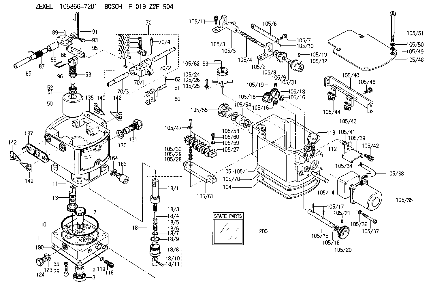
| 1. | [1] | 158502-0420 | BASE |
| 2. | [1] | 029811-8000 | BEARING PLATE |
| 3. | [1] | 158528-0900 | PACKING RING |
| 7. | [1] | 158131-0100 | GEAR SHAFT |
| 10. | [1] | 158028-0000 | O-RING |
| 11. | [1] | 158507-1920 | DIAPHRAGM HOUSING |
| 13. | [1] | 158621-0500 | SLEEVE |
| 18. | [1] | 158699-0921 | COMPENSATOR ASSY |
| 18/1. | [1] | 158610-1101 | POWER PISTON |
| 18/3. | [1] | 158654-0800 | COILED SPRING |
| 18/4. | [1] | 158614-0700 | STOP PIN |
| 18/5. | [1] | 158612-0500 | PLAIN WASHER |
| 18/6. | [1] | 158654-0900 | COILED SPRING |
| 18/7. | [1] | 016110-1220 | LOCKING WASHER |
| 18/8. | [1] | 158612-0401 | BUSHING |
| 18/9. | [2] | 016550-2310 | O-RING |
| 18/10. | [1] | 158615-0800 | PUMP PLUNGER |
| 18/11. | [1] | 025620-1410 | SPRING PIN |
| 35. | [3] | 029330-6070 | GASKET |
| 36. | [3] | 010206-2520 | HEX-SOCKET-HEAD CAP SCREW |
| 50. | [1] | 158600-1020 | FLYWEIGHT ASSEMBLY |
| 51. | [1] | 158106-0100 | PLAIN WASHER |
| 52. | [1] | 029811-0000 | BEARING PLATE |
| 53. | [1] | 158620-1420 | PILOT VALVE |
| 60. | [2] | 158220-0000 | GUIDE LEVER |
| 61. | [2] | 158736-0200 | BEARING PIN |
| 62. | [4] | 025520-1510 | SPLIT PIN |
| 70. | [1] | 158730-0220 | TERMINAL ARM |
| 70/1. | [1] | 158230-0020 | TERMINAL ARM |
| 70/2. | [1] | 158315-0200 | TERMINAL SHAFT |
| 70/3. | [1] | 158315-0200 | TERMINAL SHAFT |
| 70/4. | [2] | 158736-0100 | TAPER PIN |
| 70/5. | [2] | 011006-0620 | SET OF NUTS |
| 70/6. | [1] | 158214-0020 | SPEED DROOP ADJUSTER |
| 70/7. | [1] | 014020-5120 | PLAIN WASHER |
| 70/8. | [1] | 029320-5030 | TAB WASHER |
| 70/9. | [1] | 010535-1220 | FLAT-HEAD SCREW |
| 85. | [1] | 158814-1200 | SPEED CONTROL SHAFT |
| 86. | [1] | 158823-0300 | BUSHING |
| 87. | [1] | 158322-0200 | COILED SPRING |
| 88. | [1] | 158710-0400 | STRAP |
| 89. | [1] | 029404-5010 | BEARING PIN |
| 91. | [1] | 158712-2000 | CONTROL LEVER |
| 93. | [1] | 029010-5210 | BLEEDER SCREW |
| 95. | [1] | 158211-0100 | STRAP |
| 96. | [2] | 158653-0100 | WIRE |
| 104. | [1] | 158017-0900 | GASKET |
| 105. | [1] | 158964-5021 | GOVERNOR MOTOR ASSY |
| 105/1. | [1] | 158962-5210 | CASE |
| 105/2. | [1] | 158903-0200 | HOLDER |
| 105/3. | [1] | 158903-0300 | HOLDER |
| 105/4. | [1] | 158903-0400 | FLAT-HEAD SCREW |
| 105/5. | [1] | 158903-1720 | ADJUSTER |
| 105/6. | [2] | 158903-0800 | PLATE |
| 105/7. | [4] | 029010-6330 | BLEEDER SCREW M6P1.0L13 |
| 105/8. | [1] | 014020-8140 | PLAIN WASHER D16&8.5T1.2 |
| 105/9. | [1] | 158904-0500 | TOOTHED GEAR |
| 105/10. | [1] | 158590-0000 | BEARING PIN |
| 105/11. | [2] | 020106-1640 | BLEEDER SCREW M6P1.0L14 |
| 105/14. | [1] | 158904-0300 | LEVER SHAFT |
| 105/15. | [1] | 158904-0200 | LEVER SHAFT |
| 105/16. | [3] | 014020-8140 | PLAIN WASHER D16&8.5T1.2 |
| 105/16. | [3] | 014020-8140 | PLAIN WASHER D16&8.5T1.2 |
| 105/16. | [3] | 014020-8140 | PLAIN WASHER D16&8.5T1.2 |
| 105/17. | [3] | 015320-1540 | SPLIT PIN |
| 105/18. | [2] | 158904-0400 | TOOTHED GEAR |
| 105/18. | [2] | 158904-0400 | TOOTHED GEAR |
| 105/19. | [3] | 011005-0820 | SET OF NUTS |
| 105/19. | [3] | 011005-0820 | SET OF NUTS |
| 105/20. | [1] | 158904-1920 | ROUND NUT |
| 105/21. | [1] | 158916-0000 | SET OF NUTS |
| 105/24. | [1] | 158908-3900 | CONDENSER |
| 105/25. | [2] | 014110-3440 | LOCKING WASHER |
| 105/26. | [2] | 012153-0840 | FLAT-HEAD SCREW M3P0.5L8 |
| 105/27. | [1] | 158906-1500 | TERMINAL BOARD |
| 105/28. | [2] | 014020-4140 | PLAIN WASHER D8&4.5T0.5 |
| 105/29. | [2] | 014110-4440 | LOCKING WASHER |
| 105/30. | [2] | 012154-1040 | FLAT-HEAD SCREW M4P0.7L10 |
| 105/31. | [1] | 158902-0300 | JOINT CONNECTION |
| 105/32. | [1] | 158902-0420 | FRICTION COUPLING |
| 105/34. | [1] | 158908-2700 | GEAR HEAD |
| 105/35. | [1] | 158908-4200 | MOTOR |
| 105/36. | [4] | 014020-4140 | PLAIN WASHER D8&4.5T0.5 |
| 105/37. | [4] | 158901-8100 | FLAT-HEAD SCREW |
| 105/38. | [1] | 158901-9700 | HOSE |
| 105/39. | [1] | 158901-8300 | COVER |
| 105/40. | [1] | 158900-0300 | BRACKET |
| 105/41. | [3] | 158900-0200 | BUSHING |
| 105/42. | [3] | 029010-6350 | BLEEDER SCREW M6P1.0L22 |
| 105/43. | [1] | 158907-3820 | LIMIT SWITCH |
| 105/44. | [1] | 158907-3720 | LIMIT SWITCH |
| 105/46. | [2] | 020144-1240 | BLEEDER SCREW |
| 105/47. | [5] | 158906-0801 | TERMINAL |
| 105/48. | [1] | 158562-2600 | COVER |
| 105/49. | [4] | 014020-6140 | PLAIN WASHER |
| 105/50. | [4] | 014110-6440 | LOCKING WASHER |
| 105/51. | [4] | 158909-0100 | BLEEDER SCREW |
| 105/53. | [2] | 158901-2700 | PLAIN WASHER |
| 105/54. | [1] | 158901-2800 | PACKING |
| 105/55. | [1] | 158901-2600 | GROUND |
| 105/59. | [2] | 014110-4440 | LOCKING WASHER |
| 105/60. | [2] | 012154-1640 | FLAT-HEAD SCREW |
| 105/61. | [1] | 158906-1600 | SPACER BUSHING |
| 105/62. | [1] | 158901-2000 | WIRE |
| 105/63. | [2] | 158901-1800 | WIRE |
| 105/70. | [1] | 158563-1300 | COVER |
| 112. | [1] | 026512-1640 | GASKET D15.9&12.2T1 |
| 113. | [1] | 155406-0220 | AIR FILTER |
| 118. | [1] | 158527-0200 | NEEDLE VALVE |
| 119. | [1] | 016500-0710 | O-RING |
| 123. | [2] | 026512-1640 | GASKET D15.9&12.2T1 |
| 124. | [2] | 029111-2070 | CAPSULE M12P1.5L10 |
| 130. | [1] | 029331-8040 | GASKET |
| 131. | [1] | 158660-0320 | CONTROL VALVE |
| 135. | [1] | 158515-0900 | INDICATOR PLATE |
| 137. | [1] | 158515-1000 | INDICATOR PLATE |
| 140. | [2] | 158820-0620 | POINTER |
| 140. | [2] | 158820-0620 | POINTER |
| 142. | [2] | 158820-0620 | POINTER |
| 142. | [2] | 158820-0620 | POINTER |
| 163. | [1] | 010210-1420 | HEX-SOCKET-HEAD CAP SCREW |
| 164. | [1] | 026510-1340 | GASKET D13.4&10.2T1 |
| 190. | [1] | 158017-1000 | GASKET |
| 200. | [1] | 158599-7220 | SPARE PART |
Include in #2:
105866-7201
as INJECTION-PUMP ASSEMBLY
Cross reference number
Zexel num
Bosch num
Firm num
Name
Information:
Parts Location
Illustration 2 g01601133
(1) 308-4927 Diesel Particulate Filter and Mounting Gp (2) 235-3963 Clamp As (3) 308-4930 Bracket As (4) 8T-4183 Bolt (5) 5P-8245 Hard Washer (6) 5P-1076 Hard Washer Installation Procedure
Diesel Particulate Filter Installation
Illustration 3 g01624741
Left side view (typical example) (12) Muffler assembly (existing) (13) Bracket assembly (existing) (14) Bolt (existing) (15) Washer (existing)
Illustration 4 g01624810
Rear view (typical example) (16) Bolt (existing) (17) Hard washer (existing) (18) Muffler clamp (existing) (19) Tube assembly (existing)
Remove muffler assembly (12). Retain muffler clamp (18). The muffler clamp will be reused in Step 8. Refer to Illustrations 3 and 4.Note: A new 289-2492 Muffler Clamp (11) will be needed if the original muffler clamp cannot be reused.
Remove bracket assembly (13). Retain five bolts (14), five washers (15), two bolts (16), and two hard washers (17) that were used to secure bracket assembly (13). These parts will be reused in Step 3.
Illustration 5 g01601033
(3) 308-4930 Bracket As (4) 8T-4183 Bolt (6) 5P-1076 Hard Washer
Reuse five bolts (14), and five washers (15) to secure the new 308-4930 Bracket As (3) to the flywheel housing. Refer to Illustration 5.
Reuse two bolts (16), and two hard washers (17) to secure bracket assembly (3) to the engine lifting plate. Refer to Illustration 5.
Install two new 8T-4183 Bolts (4), and two new 5P-1076 Hard Washers (6) to the other side of bracket assembly (3) so that the bracket assembly is bolted to the engine and to the enclosure on both sides. Refer to Illustration 5.
Illustration 6 g01601025
(2) 235-3963 Clamp As (Bottom half) (4) 8T-4183 Bolt (5) 5P-8245 Hard Washer
Remove the two bolts, two hard washers, two lockwashers, and two nuts from the new 235-3963 Clamp As (2). Repeat for the other new clamp assembly (2). Retain these parts along with the upper half of the clamp assembly. These parts will be reinstalled in Step 9.
Install the bottom half of 235-3963 Clamp As (2) by using two new 8T-4183 Bolts (4) and two new 5P-8245 Hard Washers (5). Loosely secure these bolts so that the clamp assembly is adjustable. Repeat for the other clamp assembly. Refer to Illustration 6.
Illustration 7 g01601013
(1) 308-4927 Diesel Particulate Filter and Mounting Gp (2) 235-3963 Clamp As (Top half) (2a) Bolt (2b) Hard washer (2c) Lockwasher (2d) Nut (20) Inlet module tube
Install the new 308-4927 Diesel Particulate Filter and Mounting Gp (1) on top of clamp assemblies (2). The weight of the diesel particulate filter group is approximately 34 kg (75 lb). Make sure that inlet module tube (20) fits into tube assembly (19). Secure the inlet module tube to the tube assembly by using original muffler clamp (18). If the original muffler clamp (18) cannot be reused, use a new 289-2492 Muffler Clamp (11) to secure the connection. This clamp is not included in the kit. Refer to Illustration 7.
Once you have the