Information hydraulic governor
BOSCH
F 019 Z2E 444
f019z2e444
ZEXEL
105866-4230
1058664230
Rating:
Components :
| 0. | INJECTION-PUMP ASSEMBLY | 105866-4230 |
| 1. | _ | |
| 2. | FUEL INJECTION PUMP | |
| 3. | NUMBER PLATE | |
| 4. | _ | |
| 5. | CAPSULE | |
| 6. | ADJUSTING DEVICE | |
| 7. | NOZZLE AND HOLDER ASSY | |
| 8. | Nozzle and Holder | |
| 9. | Open Pre:MPa(Kqf/cm2) | |
| 10. | NOZZLE-HOLDER | |
| 11. | NOZZLE |
Scheme ###:
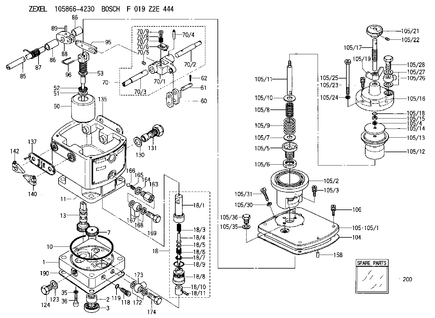
| 1. | [1] | 158502-0420 | BASE |
| 2. | [1] | 029811-8000 | BEARING PLATE |
| 3. | [1] | 158528-0900 | PACKING RING |
| 7. | [1] | 158131-0100 | GEAR SHAFT |
| 10. | [1] | 158028-0000 | O-RING |
| 11. | [1] | 158507-1920 | DIAPHRAGM HOUSING |
| 13. | [1] | 158621-0600 | SLIDING PIECE |
| 18. | [1] | 158699-0621 | COMPENSATOR ASSY |
| 18/1. | [1] | 158610-1101 | POWER PISTON |
| 18/3. | [1] | 158654-0800 | COILED SPRING |
| 18/4. | [1] | 158614-0700 | STOP PIN |
| 18/5. | [1] | 158612-0500 | PLAIN WASHER |
| 18/6. | [1] | 158654-0900 | COILED SPRING |
| 18/7. | [1] | 016110-1220 | LOCKING WASHER |
| 18/8. | [1] | 158612-0401 | BUSHING |
| 18/9. | [2] | 016550-2310 | O-RING |
| 18/10. | [1] | 158615-0500 | PUMP PLUNGER |
| 18/11. | [1] | 025620-1410 | SPRING PIN |
| 35. | [3] | 029330-6070 | GASKET |
| 36. | [3] | 010206-2520 | HEX-SOCKET-HEAD CAP SCREW |
| 50. | [1] | 158600-0720 | FLYWEIGHT ASSEMBLY |
| 51. | [1] | 158106-0100 | PLAIN WASHER |
| 52. | [1] | 029811-0000 | BEARING PLATE |
| 53. | [1] | 158620-1120 | PILOT VALVE |
| 60. | [2] | 158220-0000 | GUIDE LEVER |
| 61. | [2] | 158736-0200 | BEARING PIN |
| 62. | [4] | 025520-1510 | SPLIT PIN |
| 70. | [1] | 158730-0220 | TERMINAL ARM |
| 70/1. | [1] | 158230-0020 | TERMINAL ARM |
| 70/2. | [1] | 158315-0200 | TERMINAL SHAFT |
| 70/3. | [1] | 158315-0200 | TERMINAL SHAFT |
| 70/4. | [2] | 158736-0100 | TAPER PIN |
| 70/5. | [2] | 011006-0620 | SET OF NUTS |
| 70/6. | [1] | 158214-0020 | SPEED DROOP ADJUSTER |
| 70/7. | [1] | 014020-5120 | PLAIN WASHER |
| 70/8. | [1] | 029320-5030 | TAB WASHER |
| 70/9. | [1] | 010535-1220 | FLAT-HEAD SCREW |
| 85. | [1] | 158814-0900 | SPEED CONTROL SHAFT |
| 86. | [2] | 158823-0300 | BUSHING |
| 86. | [2] | 158823-0300 | BUSHING |
| 87. | [1] | 158322-0200 | COILED SPRING |
| 88. | [1] | 158710-0400 | STRAP |
| 89. | [1] | 029404-5010 | BEARING PIN |
| 95. | [1] | 158211-0100 | STRAP |
| 96. | [2] | 158653-0100 | WIRE |
| 104. | [1] | 158017-0900 | GASKET |
| 105. | [1] | 158562-7020 | PNEUMATIC CONTROLLER |
| 105/1. | [1] | 158562-4600 | COVER |
| 105/2. | [1] | 158910-0200 | CYLINDER |
| 105/3. | [3] | 029050-6090 | FLAT-HEAD SCREW |
| 105/4. | [1] | 014110-6440 | LOCKING WASHER |
| 105/5. | [1] | 158416-0000 | FLAT-HEAD SCREW |
| 105/6. | [1] | 158915-0700 | UNION NUT |
| 105/7. | [1] | 158918-0000 | PLAIN WASHER D30&10.8T1.00 |
| 105/8. | [1] | 158412-0200 | COILED SPRING K2.0 |
| 105/9. | [1] | 158912-0600 | COILED SPRING K5.1 |
| 105/9B. | [1] | 158912-0500 | COILED SPRING K4.9 |
| 105/9C. | [1] | 158912-0700 | COILED SPRING K5.2 |
| 105/9D. | [1] | 158912-1100 | COILED SPRING K4.8 |
| 105/9E. | [1] | 158912-1200 | COILED SPRING K5.4 |
| 105/10. | [1] | 158918-0000 | PLAIN WASHER D30&10.8T1.00 |
| 105/11. | [1] | 158413-0001 | STOP PIN |
| 105/12. | [1] | 158414-0000 | PUMP PLUNGER |
| 105/13. | [1] | 158414-0100 | DIAPHRAGM |
| 105/14. | [1] | 158414-0200 | PLATE |
| 105/15. | [1] | 013020-6040 | UNION NUT M6P1H5 |
| 105/16. | [1] | 158910-0300 | CAP |
| 105/17. | [1] | 158915-1000 | FLAT-HEAD SCREW |
| 105/18. | [1] | 029630-9050 | O-RING |
| 105/19. | [1] | 158567-1500 | WING NUT |
| 105/21. | [1] | 158904-2020 | ROUND NUT |
| 105/22. | [1] | 158916-0000 | SET OF NUTS |
| 105/23. | [2] | 029050-6220 | FLAT-HEAD SCREW |
| 105/24. | [2] | 029320-6010 | LOCKING WASHER |
| 105/25. | [2] | 158909-0200 | BLEEDER SCREW |
| 105/26. | [1] | 027114-1040 | INLET UNION |
| 105/27. | [2] | 029331-4120 | GASKET D18&14.2T1.5 |
| 105/28. | [1] | 027414-2640 | EYE BOLT |
| 105/30. | [1] | 013020-6040 | UNION NUT M6P1H5 |
| 105/31. | [1] | 158567-1200 | SET OF NUTS |
| 105/35. | [1] | 026512-1640 | GASKET D15.9&12.2T1 |
| 105/36. | [1] | 158066-0000 | BLEEDER SCREW |
| 106. | [4] | 029010-6350 | BLEEDER SCREW M6P1.0L22 |
| 118. | [1] | 158527-0200 | NEEDLE VALVE |
| 119. | [1] | 016500-0710 | O-RING |
| 123. | [1] | 026512-1640 | GASKET D15.9&12.2T1 |
| 124. | [1] | 029111-2070 | CAPSULE M12P1.5L10 |
| 130. | [1] | 029331-8040 | GASKET |
| 131. | [1] | 158660-0320 | CONTROL VALVE |
| 135. | [1] | 158515-0900 | INDICATOR PLATE |
| 137. | [1] | 158515-1000 | INDICATOR PLATE |
| 140. | [1] | 158820-0620 | POINTER |
| 142. | [1] | 158820-0620 | POINTER |
| 158. | [1] | 015040-0880 | BEARING PIN |
| 163. | [1] | 158522-0000 | CONNECTOR |
| 164. | [1] | 026510-1340 | GASKET D13.4&10.2T1 |
| 165. | [1] | 158655-0000 | COILED SPRING |
| 166. | [1] | 029820-6010 | BALL |
| 167. | [1] | 026512-1840 | GASKET D17.9&12.2T1.50 |
| 168. | [1] | 029701-2030 | INLET UNION |
| 169. | [1] | 158521-0000 | EYE BOLT |
| 172. | [2] | 026512-1640 | GASKET D15.9&12.2T1 |
| 173. | [1] | 029701-2030 | INLET UNION |
| 174. | [1] | 027412-2440 | EYE BOLT |
| 190. | [1] | 158017-1000 | GASKET |
| 200. | [1] | 158599-7320 | SPARE PART |
Include in #2:
105866-4230
as INJECTION-PUMP ASSEMBLY
Cross reference number
Zexel num
Bosch num
Firm num
Name
105866-4230
HYDRAULIC GOVERNOR
K 35CA HYDRAULIC GOVERNOR Hydraulic RHD10 Others
K 35CA HYDRAULIC GOVERNOR Hydraulic RHD10 Others
Information:
Diagnostic Lamp
A DIAGNOSTIC lamp may be included with your engine package. The DIAGNOSTIC lamp indicates an engine diagnostic condition or an electronic governing/control system fault. In most cases a diagnostic code will be stored in permanent memory within the ECM. The diagnostic code can be retrieved by either of two methods; 1) electronic service tool or 2) use the DIAGNOSTIC lamp.The engine may be equipped with a DIAGNOSTIC lamp that automatically flashes an active fault code when there is power to the ECM. ACTIVE Codes - represent problem(s) that currently exist and should be investigated first. If a code is active, the Diagnostic lamp will illuminate and blink every five seconds. LOGGED Codes - represent intermittent problem(s) which may have been temporary or repaired since the time code was logged. These codes do not indicate a repair is needed, but instead are guides or signals when an intermittent situation exists, which could be used to troubleshoot and analyze potential problems. In addition, some LOGGED Codes record events and performance history, rather than problems and/or failures.Diagnostic Flash Code Retrieval
If the DIAGNOSTIC lamp is ON during engine operation, the system has detected a system fault. Use the DIAGNOSTIC lamp or electronic service tool to identify the diagnostic code.The DIAGNOSTIC lamp will illuminate (ON) and blink every five seconds whenever a diagnostic fault is detected by the ECM. The lamp should also illuminate (ON) whenever the START switch is turned ON, but the engine is not running. This condition will test whether the lamp is operating correctly. The DIAGNOSTIC lamp will illuminate for five seconds and turn OFF for an intermittent fault (stays ON ONLY if there is an Active Diagnostic Code).If the DIAGNOSTIC lamp comes ON and stays ON after initial start-up, the ECM has detected a system fault. Use the lamp or the ECAP service tool to determine the diagnostic code.The DIAGNOSTIC lamp can be used to communicate the specific diagnostic fault. With the switch depressed, the DIAGNOSTIC lamp will begin to flash. The sequence of flashes represents the system diagnostic message. Count the first sequence of flashes to determine the first digit of the diagnostic code. After a two second pause, the second sequence of flashes will identify the second digit of the diagnostic code. Any additional diagnostic codes will follow (after a pause) and will be displayed in the same manner.Refer to the Electronic Troubleshooting Manual for troubleshooting ELECTRONIC SYSTEM problems, or for further information or assistance, contact your Caterpillar dealer. Permanent Fault Logging
The system provides Permanent Fault Logging. When the ECM generates a diagnostic code, it will log the code in permanent memory. The logged codes can then be retrieved using an electronic service tool.Intermittent Fault
If the diagnostic lamp comes ON during engine operation, and then goes out, an intermittent fault may be occurring. The electronic control engine system is equipped with permanent fault logging. It will automatically log (or remember) most intermittent faults to help a service technician diagnose an engine problem.If there are no