Information hydraulic governor
BOSCH
F 019 Z2E 417
f019z2e417
ZEXEL
105866-3200
1058663200
Rating:
Components :
| 0. | INJECTION-PUMP ASSEMBLY | 105866-3200 |
| 1. | _ | |
| 2. | FUEL INJECTION PUMP | |
| 3. | NUMBER PLATE | |
| 4. | _ | |
| 5. | CAPSULE | |
| 6. | ADJUSTING DEVICE | |
| 7. | NOZZLE AND HOLDER ASSY | |
| 8. | Nozzle and Holder | |
| 9. | Open Pre:MPa(Kqf/cm2) | |
| 10. | NOZZLE-HOLDER | |
| 11. | NOZZLE |
Scheme ###:
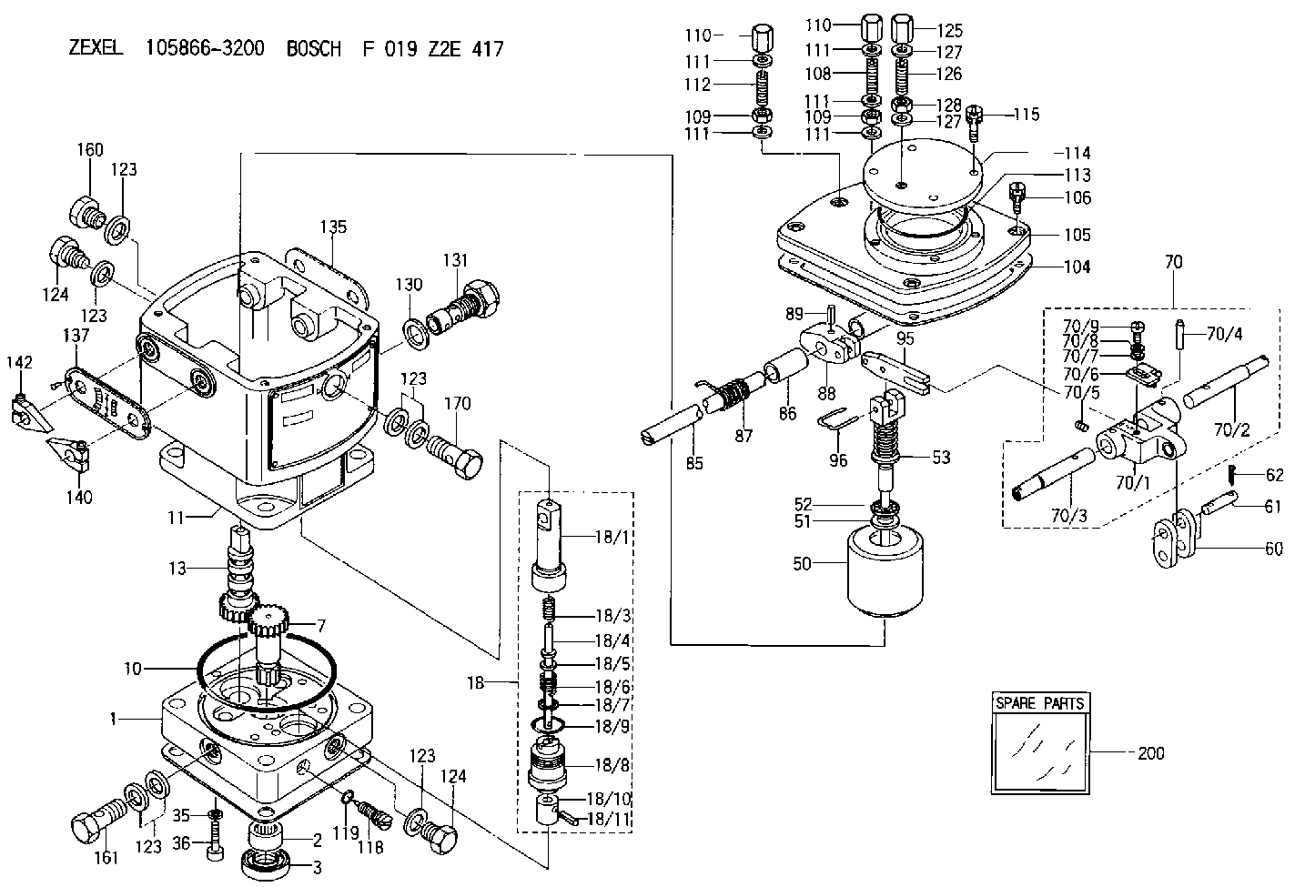
| 1. | [1] | 158502-0620 | BASE |
| 2. | [1] | 029811-8000 | BEARING PLATE |
| 3. | [1] | 158528-0900 | PACKING RING |
| 7. | [1] | 158131-0100 | GEAR SHAFT |
| 10. | [1] | 158028-0000 | O-RING |
| 11. | [1] | 158507-1620 | DIAPHRAGM HOUSING |
| 13. | [1] | 158621-0500 | SLEEVE |
| 18. | [1] | 158699-0921 | COMPENSATOR ASSY |
| 18/1. | [1] | 158610-1101 | POWER PISTON |
| 18/3. | [1] | 158654-0800 | COILED SPRING |
| 18/4. | [1] | 158614-0700 | STOP PIN |
| 18/5. | [1] | 158612-0500 | PLAIN WASHER |
| 18/6. | [1] | 158654-0900 | COILED SPRING |
| 18/7. | [1] | 016110-1220 | LOCKING WASHER |
| 18/8. | [1] | 158612-0401 | BUSHING |
| 18/9. | [2] | 016550-2310 | O-RING |
| 18/10. | [1] | 158615-0800 | PUMP PLUNGER |
| 18/11. | [1] | 025620-1410 | SPRING PIN |
| 35. | [3] | 029330-6070 | GASKET |
| 36. | [3] | 010206-2520 | HEX-SOCKET-HEAD CAP SCREW |
| 50. | [1] | 158600-1120 | FLYWEIGHT ASSEMBLY |
| 51. | [1] | 158106-0100 | PLAIN WASHER |
| 52. | [1] | 029811-0000 | BEARING PLATE |
| 53. | [1] | 158620-1120 | PILOT VALVE |
| 60. | [1] | 158720-0000 | GUIDE LEVER |
| 61. | [2] | 158736-0200 | BEARING PIN |
| 62. | [4] | 025520-1510 | SPLIT PIN |
| 70. | [1] | 158730-0920 | TERMINAL ARM |
| 70/1. | [1] | 158230-0020 | TERMINAL ARM |
| 70/2. | [1] | 158815-0700 | TERMINAL SHAFT |
| 70/3. | [1] | 158815-0600 | TERMINAL SHAFT |
| 70/4. | [2] | 158736-0100 | TAPER PIN |
| 70/5. | [2] | 011006-0620 | SET OF NUTS |
| 70/6. | [1] | 158214-0020 | SPEED DROOP ADJUSTER |
| 70/7. | [1] | 014020-5120 | PLAIN WASHER |
| 70/8. | [1] | 029320-5030 | TAB WASHER |
| 70/9. | [1] | 010535-1220 | FLAT-HEAD SCREW |
| 85. | [1] | 158814-1800 | SPEED CONTROL SHAFT |
| 86. | [2] | 158823-0300 | BUSHING |
| 87. | [1] | 158322-0200 | COILED SPRING |
| 88. | [1] | 158710-0400 | STRAP |
| 89. | [1] | 029404-5010 | BEARING PIN |
| 95. | [1] | 158211-0100 | STRAP |
| 96. | [2] | 158653-0100 | WIRE |
| 104. | [1] | 158017-0900 | GASKET |
| 105. | [1] | 158563-0600 | COVER |
| 106. | [4] | 029010-6350 | BLEEDER SCREW M6P1.0L22 |
| 108. | [1] | 158567-2000 | FLAT-HEAD SCREW |
| 109. | [2] | 013020-6040 | UNION NUT M6P1H5 |
| 109. | [2] | 013020-6040 | UNION NUT M6P1H5 |
| 110. | [2] | 158567-1900 | CAP NUT |
| 110. | [2] | 158567-1900 | CAP NUT |
| 111. | [4] | 026506-1040 | GASKET D9.9&6.2T1 |
| 111. | [4] | 026506-1040 | GASKET D9.9&6.2T1 |
| 111. | [4] | 026506-1040 | GASKET D9.9&6.2T1 |
| 111. | [4] | 026506-1040 | GASKET D9.9&6.2T1 |
| 111. | [4] | 026506-1040 | GASKET D9.9&6.2T1 |
| 112. | [1] | 158567-2100 | FLAT-HEAD SCREW |
| 113. | [1] | 016510-6510 | O-RING |
| 114. | [1] | 158563-0700 | COVER |
| 115. | [4] | 029010-6340 | BLEEDER SCREW M6P1.0L16 |
| 118. | [1] | 158027-0100 | NEEDLE VALVE |
| 119. | [1] | 016500-0710 | O-RING |
| 123. | [6] | 026512-1640 | GASKET D15.9&12.2T1 |
| 123. | [6] | 026512-1640 | GASKET D15.9&12.2T1 |
| 123. | [6] | 026512-1640 | GASKET D15.9&12.2T1 |
| 123. | [6] | 026512-1640 | GASKET D15.9&12.2T1 |
| 123. | [6] | 026512-1640 | GASKET D15.9&12.2T1 |
| 124. | [2] | 029111-2070 | CAPSULE M12P1.5L10 |
| 124. | [2] | 029111-2070 | CAPSULE M12P1.5L10 |
| 125. | [1] | 158067-0300 | CAP NUT |
| 126. | [1] | 158067-0200 | SET OF NUTS |
| 127. | [2] | 026508-1140 | GASKET D11.4&8.2T1 |
| 127. | [2] | 026508-1140 | GASKET D11.4&8.2T1 |
| 128. | [1] | 158565-0000 | UNION NUT |
| 130. | [1] | 029331-8040 | GASKET |
| 131. | [1] | 158660-0520 | CONTROL VALVE |
| 135. | [1] | 158515-0900 | INDICATOR PLATE |
| 137. | [1] | 158515-1000 | INDICATOR PLATE |
| 140. | [1] | 158820-0620 | POINTER |
| 142. | [1] | 158820-0620 | POINTER |
| 160. | [1] | 029111-2070 | CAPSULE M12P1.5L10 |
| 161. | [1] | 158521-0600 | EYE BOLT |
| 170. | [1] | 158521-0700 | EYE BOLT |
| 200. | [1] | 158599-5520 | SPARE PART |
Include in #2:
105866-3200
as INJECTION-PUMP ASSEMBLY
Cross reference number
Zexel num
Bosch num
Firm num
Name
105866-3200
HYDRAULIC GOVERNOR
K 35CA HYDRAULIC GOVERNOR Hydraulic RHD10 Others
K 35CA HYDRAULIC GOVERNOR Hydraulic RHD10 Others
Information:
Startability will be improved at temperatures below +32°F (0°C) by the use of a starting aid and/or use of a cylinder block coolant heater or other means to heat the crankcase oil.Start the engine using the following procedure:1. Place the transmission in NEUTRAL and disengage the flywheel clutch (if equipped) to remove the transmission drag and prevent movement of the truck. Depressing the clutch in cold weather can mean the difference between starting and not starting. Depressing the clutch in warm weather produces faster starts and reduces battery drain.2. Turn the ignition switch to the ON position and push the crank button or turn the ignition switch to the START position. Crank the engine. (At temperatures below +32°F (0°C), it may be necessary to spray starting fluid into the air cleaner inlet.) DO NOT PUSH DOWN OR HOLD THE THROTTLE DOWN while cranking the engine. The 3176 system will automatically provide the correct amount of fuel to start the engine. The engine may need to crank slightly longer than a mechanically governed engine, because some oil pressure is required for the electronic actuator to move the rack. The "CHECK ENGINE" light should beON while the engine is cranking, but should go OFF after the engine starts and operating oil pressure is achieved.If the engine fails to start in 30 seconds, release the starter switch and wait two minutes to allow the starter motor to cool before using it again.
When using starting fluid, follow the manufacturer's instructions carefully, use it sparingly and spray it only while cranking the engine. Also, do not store starting fluid containers in the cab. Failure todo so, could result in an explosion and/or fire and possible personal injury.
Excessive ether can cause piston and ring damage. Use ether for cold starting purposes only.
3. As soon as the engine starts, allow the engine to idle for two or three minutes, or until the water temperature gauge indicator has begun to rise.4. Do not apply load to the engine or increase engine speed until the oil pressure gauge indicates normal. Oil pressure should rise within 15 seconds after the engine starts.5. Operate the engine at low load until all systems reach operating temperature. Check all gauges during the warm-up period.Starting With Jumper Cables
Batteries give off flammable fumes that can explode.Improper jumper cable connections can cause an explosion resulting in personal injury.Prevent sparks near the batteries. Sparks could cause vapors to explode. Do not allow jumper cable ends to contact each other or the engine.Do not smoke when observing the battery electrolyte levels.Always wear protective glasses when working with batteries.Electrolyte is an acid and can cause personal injury if it contacts skin or eyes.
Engines installed without engine-to-frame ground straps can be damaged by electrical discharge.To prevent electrical discharge damage, check to make sure the engine's electrical system has an engine-to-frame ground strap. For engines which have the alternator connected to an engine component, the ground strap must connect that component to thframe.Some engines have starter-to-frame ground straps.