Information hydraulic governor
BOSCH
F 019 Z2E 416
f019z2e416
ZEXEL
105866-3190
1058663190
Rating:
Components :
| 0. | INJECTION-PUMP ASSEMBLY | 105866-3190 |
| 1. | _ | |
| 2. | FUEL INJECTION PUMP | |
| 3. | NUMBER PLATE | |
| 4. | _ | |
| 5. | CAPSULE | |
| 6. | ADJUSTING DEVICE | |
| 7. | NOZZLE AND HOLDER ASSY | |
| 8. | Nozzle and Holder | |
| 9. | Open Pre:MPa(Kqf/cm2) | |
| 10. | NOZZLE-HOLDER | |
| 11. | NOZZLE |
Scheme ###:
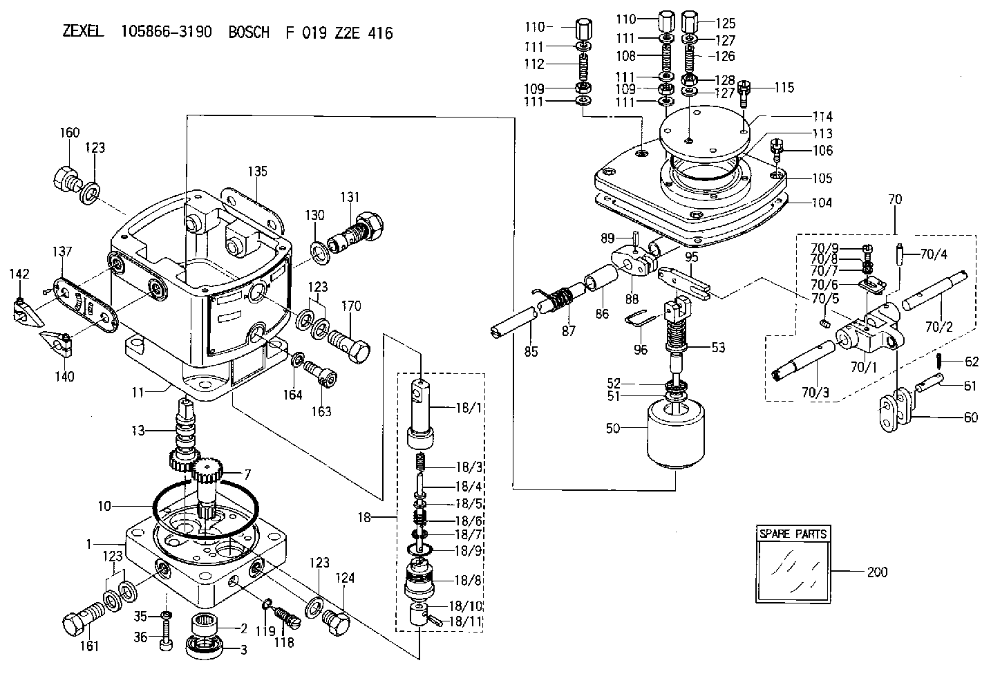
| 1. | [1] | 158502-0620 | BASE |
| 2. | [1] | 029811-8000 | BEARING PLATE |
| 3. | [1] | 158528-0900 | PACKING RING |
| 7. | [1] | 158131-0100 | GEAR SHAFT |
| 10. | [1] | 158028-0000 | O-RING |
| 11. | [1] | 158507-1520 | DIAPHRAGM HOUSING |
| 13. | [1] | 158621-0500 | SLEEVE |
| 18. | [1] | 158699-0921 | COMPENSATOR ASSY |
| 18/1. | [1] | 158610-1101 | POWER PISTON |
| 18/3. | [1] | 158654-0800 | COILED SPRING |
| 18/4. | [1] | 158614-0700 | STOP PIN |
| 18/5. | [1] | 158612-0500 | PLAIN WASHER |
| 18/6. | [1] | 158654-0900 | COILED SPRING |
| 18/7. | [1] | 016110-1220 | LOCKING WASHER |
| 18/8. | [1] | 158612-0401 | BUSHING |
| 18/9. | [2] | 016550-2310 | O-RING |
| 18/10. | [1] | 158615-0800 | PUMP PLUNGER |
| 18/11. | [1] | 025620-1410 | SPRING PIN |
| 35. | [3] | 029330-6070 | GASKET |
| 36. | [3] | 010206-2520 | HEX-SOCKET-HEAD CAP SCREW |
| 50. | [1] | 158600-1120 | FLYWEIGHT ASSEMBLY |
| 51. | [1] | 158106-0100 | PLAIN WASHER |
| 52. | [1] | 029811-0000 | BEARING PLATE |
| 53. | [1] | 158620-1120 | PILOT VALVE |
| 60. | [1] | 158720-0000 | GUIDE LEVER |
| 61. | [2] | 158736-0200 | BEARING PIN |
| 62. | [4] | 025520-1510 | SPLIT PIN |
| 70. | [1] | 158730-0920 | TERMINAL ARM |
| 70/1. | [1] | 158230-0020 | TERMINAL ARM |
| 70/2. | [1] | 158815-0700 | TERMINAL SHAFT |
| 70/3. | [1] | 158815-0600 | TERMINAL SHAFT |
| 70/4. | [2] | 158736-0100 | TAPER PIN |
| 70/5. | [2] | 011006-0620 | SET OF NUTS |
| 70/6. | [1] | 158214-0020 | SPEED DROOP ADJUSTER |
| 70/7. | [1] | 014020-5120 | PLAIN WASHER |
| 70/8. | [1] | 029320-5030 | TAB WASHER |
| 70/9. | [1] | 010535-1220 | FLAT-HEAD SCREW |
| 85. | [1] | 158814-1800 | SPEED CONTROL SHAFT |
| 86. | [2] | 158823-0300 | BUSHING |
| 87. | [1] | 158322-0200 | COILED SPRING |
| 88. | [1] | 158710-0400 | STRAP |
| 89. | [1] | 029404-5010 | BEARING PIN |
| 95. | [1] | 158211-0100 | STRAP |
| 96. | [2] | 158653-0100 | WIRE |
| 104. | [1] | 158017-0900 | GASKET |
| 105. | [1] | 158563-0600 | COVER |
| 106. | [4] | 029010-6350 | BLEEDER SCREW M6P1.0L22 |
| 108. | [1] | 158567-2000 | FLAT-HEAD SCREW |
| 109. | [2] | 013020-6040 | UNION NUT M6P1H5 |
| 109. | [2] | 013020-6040 | UNION NUT M6P1H5 |
| 110. | [2] | 158567-1900 | CAP NUT |
| 110. | [2] | 158567-1900 | CAP NUT |
| 111. | [4] | 026506-1040 | GASKET D9.9&6.2T1 |
| 111. | [4] | 026506-1040 | GASKET D9.9&6.2T1 |
| 111. | [4] | 026506-1040 | GASKET D9.9&6.2T1 |
| 111. | [4] | 026506-1040 | GASKET D9.9&6.2T1 |
| 111. | [4] | 026506-1040 | GASKET D9.9&6.2T1 |
| 112. | [1] | 158567-2100 | FLAT-HEAD SCREW |
| 113. | [1] | 016510-6510 | O-RING |
| 114. | [1] | 158563-0700 | COVER |
| 115. | [1] | 029010-6340 | BLEEDER SCREW M6P1.0L16 |
| 118. | [1] | 158027-0100 | NEEDLE VALVE |
| 119. | [1] | 016500-0710 | O-RING |
| 123. | [6] | 026512-1640 | GASKET D15.9&12.2T1 |
| 123. | [6] | 026512-1640 | GASKET D15.9&12.2T1 |
| 123. | [6] | 026512-1640 | GASKET D15.9&12.2T1 |
| 123. | [6] | 026512-1640 | GASKET D15.9&12.2T1 |
| 124. | [2] | 029111-2070 | CAPSULE M12P1.5L10 |
| 125. | [1] | 158067-0300 | CAP NUT |
| 126. | [1] | 158067-0200 | SET OF NUTS |
| 127. | [2] | 026508-1140 | GASKET D11.4&8.2T1 |
| 127. | [2] | 026508-1140 | GASKET D11.4&8.2T1 |
| 128. | [1] | 158565-0000 | UNION NUT |
| 130. | [1] | 029331-8040 | GASKET |
| 131. | [1] | 158660-0520 | CONTROL VALVE |
| 135. | [1] | 158515-0900 | INDICATOR PLATE |
| 137. | [1] | 158515-1000 | INDICATOR PLATE |
| 140. | [1] | 158820-0620 | POINTER |
| 142. | [1] | 158820-0620 | POINTER |
| 160. | [1] | 029111-2070 | CAPSULE M12P1.5L10 |
| 161. | [1] | 158521-0600 | EYE BOLT |
| 163. | [1] | 010210-1420 | HEX-SOCKET-HEAD CAP SCREW |
| 164. | [1] | 026510-1340 | GASKET D13.4&10.2T1 |
| 170. | [1] | 158521-0700 | EYE BOLT |
| 200. | [1] | 158599-5520 | SPARE PART |
Include in #2:
105866-3190
as INJECTION-PUMP ASSEMBLY
Cross reference number
Zexel num
Bosch num
Firm num
Name
105866-3190
F 019 Z2E 416
HYDRAULIC GOVERNOR
* K 35CA Hydraulic RHD10 Others
* K 35CA Hydraulic RHD10 Others
Information:
Under the Hood Inspection
For maximum service life of your truck engine, make a thorough under the hood inspection before starting the engine. Look for oil or coolant leaks, loose bolts, worn fan belts and trash build-up. Remove trash build-up and have repairs made as needed. * Inspect the radiator for leaks and trash build-up. * Inspect the radiator hoses for cracks and loose clamps.* Inspect the fan and accessory drive belts for cracks, breaks or other damage. Belts for multiple groove pulleys are sold in matched sets. Belts for multiple groove pulleys must be replaced as matched sets. If only one belt of a two or three belt set is replaced, it will carry more of a load than the belts not replaced since the older belts are stretched. The additional load on the new belt could cause it to break. * Inspect the water pump for leaks. The water pump seal is lubricated by coolant in the cooling system. It is normal for a small amount of leakage to occur as the engine cools down and parts contract. * Inspect the engine for oil leaks, such as front and rear crankshaft seals, crankcase, oil filter and valve covers.* Inspect the fuel system for leaks, loose fuel line clamps and fittings and loose or worn hoses. If leaking is observed, find the source and correct the leak. If leaking is suspected, check the fluid levels more frequently than the recommended service intervals prescribed in this publication until a leak is found or fixed, or until the suspicion for a leak has been proven to be unwarranted. * Inspect wiring for loose connections and worn or frayed wires.* Inspect ATAAC and air intake system hoses and elbows for cracks and loose clamps.* Inspect engine-to-frame ground strap for good connection and condition.Pre-Start Checks
* Measure the engine crankcase oil level. The correct oil level is shown by the marks between the words "ADD" and "FULL RANGE" on the dipstick (oil level gauge) on the "Engine Stopped" side.The location of the ADD and FULL RANGE marks on the engine dipstick are determined by the tilt angle of the engine after it is installed in the truck.If the ADD and FULL RANGE marks have not been stamped on the dipstick, see "Calibration" in the "Dipsticks" section of this manual or contact your Caterpillar dealer. * Check the coolant level with the engine stopped and cold. Remove the filler cap slowly to relieve pressure.* Maintain the coolant level to within 1/2 inch (13 mm) of the bottom of the fill pipe. Install the filler cap.* If equipped with a sight glass, maintain the coolant to the proper level.
To prevent engine damage, never add coolant to an overheated engine. Allow the engine to cool first.
Typical Example* Observe the air cleaner service indicator (if equipped). Service the air cleaner when the yellow diaphragm enters the red zone or the red piston locks in the visible position. If your truck air cleaner is not equipped with an
Have questions with 105866-3190?
Group cross 105866-3190 ZEXEL
Mitsubishi-Heav
Hanshin
Fuji-Diesel
105866-3190
F 019 Z2E 416
HYDRAULIC GOVERNOR