Information hydraulic governor
BOSCH
F 019 Z1F 221
f019z1f221
ZEXEL
105856-7891
1058567891
Rating:
Components :
| 0. | INJECTION-PUMP ASSEMBLY | 105856-7891 |
| 1. | _ | |
| 2. | FUEL INJECTION PUMP | |
| 3. | NUMBER PLATE | |
| 4. | _ | |
| 5. | CAPSULE | |
| 6. | ADJUSTING DEVICE | |
| 7. | NOZZLE AND HOLDER ASSY | |
| 8. | Nozzle and Holder | |
| 9. | Open Pre:MPa(Kqf/cm2) | |
| 10. | NOZZLE-HOLDER | |
| 11. | NOZZLE |
Scheme ###:
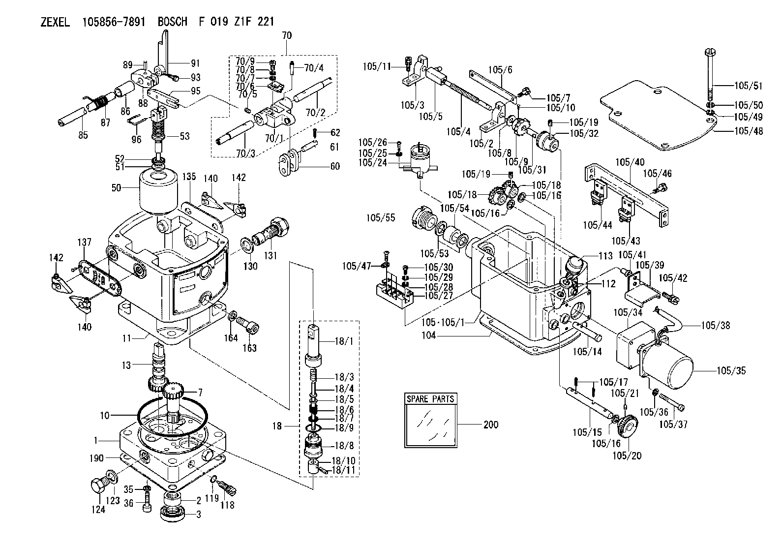
| 1. | [1] | 158502-0420 | BASE |
| 2. | [1] | 029811-8000 | BEARING PLATE |
| 3. | [1] | 158528-0900 | PACKING RING |
| 7. | [1] | 158131-0100 | GEAR SHAFT |
| 10. | [1] | 158028-0000 | O-RING |
| 11. | [1] | 158507-1120 | DIAPHRAGM HOUSING |
| 13. | [1] | 158621-0800 | SLEEVE |
| 18. | [1] | 158699-0521 | COMPENSATOR ASSY |
| 18/1. | [1] | 158610-0901 | POWER PISTON |
| 18/3. | [1] | 158654-1000 | COILED SPRING |
| 18/4. | [1] | 158614-0300 | STOP PIN |
| 18/5. | [1] | 158612-0500 | PLAIN WASHER |
| 18/6. | [1] | 158654-1100 | COILED SPRING |
| 18/7. | [1] | 016110-1220 | LOCKING WASHER |
| 18/8. | [1] | 158612-0001 | BUSHING |
| 18/9. | [2] | 158528-1300 | O-RING |
| 18/10. | [1] | 158615-0400 | PUMP PLUNGER |
| 18/11. | [1] | 025620-1410 | SPRING PIN |
| 35. | [3] | 029330-6070 | GASKET |
| 36. | [3] | 010206-2520 | HEX-SOCKET-HEAD CAP SCREW |
| 50. | [1] | 158600-1020 | FLYWEIGHT ASSEMBLY |
| 51. | [1] | 158106-0100 | PLAIN WASHER |
| 52. | [1] | 029811-0000 | BEARING PLATE |
| 53. | [1] | 158620-1220 | PILOT VALVE |
| 60. | [2] | 158220-0000 | GUIDE LEVER |
| 61. | [2] | 158736-0200 | BEARING PIN |
| 62. | [4] | 025520-1510 | SPLIT PIN |
| 70. | [1] | 158730-0220 | TERMINAL ARM |
| 70/1. | [1] | 158230-0020 | TERMINAL ARM |
| 70/2. | [1] | 158315-0200 | TERMINAL SHAFT |
| 70/3. | [1] | 158315-0200 | TERMINAL SHAFT |
| 70/4. | [2] | 158736-0100 | TAPER PIN |
| 70/5. | [2] | 011006-0620 | SET OF NUTS |
| 70/6. | [1] | 158214-0020 | SPEED DROOP ADJUSTER |
| 70/7. | [1] | 014020-5120 | PLAIN WASHER |
| 70/8. | [1] | 029320-5030 | TAB WASHER |
| 70/9. | [1] | 010535-1220 | FLAT-HEAD SCREW |
| 85. | [1] | 158814-1200 | SPEED CONTROL SHAFT |
| 86. | [1] | 158823-0300 | BUSHING |
| 87. | [1] | 158322-0200 | COILED SPRING |
| 88. | [1] | 158710-0400 | STRAP |
| 89. | [1] | 029404-5010 | BEARING PIN |
| 91. | [1] | 158712-2000 | CONTROL LEVER |
| 93. | [1] | 029010-5210 | BLEEDER SCREW |
| 95. | [1] | 158211-0100 | STRAP |
| 96. | [2] | 158653-0100 | WIRE |
| 104. | [1] | 158017-0900 | GASKET |
| 105. | [1] | 158964-9820 | GOVERNOR MOTOR ASSY |
| 105/1. | [1] | 158962-5210 | CASE |
| 105/2. | [1] | 158903-0200 | HOLDER |
| 105/3. | [1] | 158903-0300 | HOLDER |
| 105/4. | [1] | 158903-0400 | FLAT-HEAD SCREW |
| 105/5. | [1] | 158903-1720 | ADJUSTER |
| 105/6. | [2] | 158903-0800 | PLATE |
| 105/7. | [4] | 029010-6330 | BLEEDER SCREW M6P1.0L13 |
| 105/8. | [1] | 014020-8140 | PLAIN WASHER D16&8.5T1.2 |
| 105/9. | [1] | 158904-0500 | TOOTHED GEAR |
| 105/10. | [1] | 158590-0000 | BEARING PIN |
| 105/11. | [2] | 020106-1640 | BLEEDER SCREW M6P1.0L14 |
| 105/14. | [1] | 158904-0300 | LEVER SHAFT |
| 105/15. | [1] | 158904-0200 | LEVER SHAFT |
| 105/16. | [3] | 014020-8140 | PLAIN WASHER D16&8.5T1.2 |
| 105/16. | [3] | 014020-8140 | PLAIN WASHER D16&8.5T1.2 |
| 105/16. | [3] | 014020-8140 | PLAIN WASHER D16&8.5T1.2 |
| 105/17. | [3] | 015320-1540 | SPLIT PIN |
| 105/18. | [2] | 158904-0400 | TOOTHED GEAR |
| 105/18. | [2] | 158904-0400 | TOOTHED GEAR |
| 105/19. | [3] | 011005-0820 | SET OF NUTS |
| 105/19. | [3] | 011005-0820 | SET OF NUTS |
| 105/20. | [1] | 158904-1920 | ROUND NUT |
| 105/21. | [1] | 158916-0000 | SET OF NUTS |
| 105/24. | [1] | 158908-3900 | CONDENSER |
| 105/25. | [2] | 014110-3440 | LOCKING WASHER |
| 105/26. | [2] | 012153-0840 | FLAT-HEAD SCREW M3P0.5L8 |
| 105/27. | [1] | 158906-0700 | TERMINAL BOARD |
| 105/28. | [2] | 014020-4140 | PLAIN WASHER D8&4.5T0.5 |
| 105/29. | [2] | 014110-4440 | LOCKING WASHER |
| 105/30. | [2] | 012154-1640 | FLAT-HEAD SCREW |
| 105/31. | [1] | 158902-0300 | JOINT CONNECTION |
| 105/32. | [1] | 158902-0020 | FRICTION COUPLING |
| 105/34. | [1] | 158908-5400 | GEAR HEAD |
| 105/35. | [1] | 158908-5020 | MOTOR |
| 105/36. | [4] | 014020-4140 | PLAIN WASHER D8&4.5T0.5 |
| 105/37. | [4] | 158901-8100 | FLAT-HEAD SCREW |
| 105/38. | [1] | 158901-2200 | HOSE |
| 105/39. | [1] | 158901-8300 | COVER |
| 105/40. | [1] | 158900-0300 | BRACKET |
| 105/41. | [3] | 158900-0200 | BUSHING |
| 105/42. | [3] | 029010-6350 | BLEEDER SCREW M6P1.0L22 |
| 105/43. | [1] | 158907-1820 | LIMIT SWITCH |
| 105/44. | [1] | 158907-1720 | LIMIT SWITCH |
| 105/46. | [4] | 020144-1240 | BLEEDER SCREW |
| 105/47. | [1] | 158906-0801 | TERMINAL |
| 105/48. | [1] | 158562-2600 | COVER |
| 105/49. | [4] | 014020-6140 | PLAIN WASHER |
| 105/50. | [4] | 014110-6440 | LOCKING WASHER |
| 105/51. | [4] | 158909-0100 | BLEEDER SCREW |
| 105/53. | [2] | 158901-2700 | PLAIN WASHER |
| 105/54. | [1] | 158901-2800 | PACKING |
| 105/55. | [1] | 158901-2600 | GROUND |
| 112. | [1] | 026512-1640 | GASKET D15.9&12.2T1 |
| 113. | [1] | 155406-0220 | AIR FILTER |
| 118. | [1] | 158527-0200 | NEEDLE VALVE |
| 119. | [1] | 016500-0710 | O-RING |
| 123. | [2] | 026512-1640 | GASKET D15.9&12.2T1 |
| 124. | [2] | 029111-2070 | CAPSULE M12P1.5L10 |
| 130. | [1] | 029331-8040 | GASKET |
| 131. | [1] | 158660-0320 | CONTROL VALVE |
| 135. | [1] | 158515-0700 | INDICATOR PLATE |
| 137. | [1] | 158515-0800 | INDICATOR PLATE |
| 140. | [2] | 158820-0620 | POINTER |
| 140. | [2] | 158820-0620 | POINTER |
| 142. | [2] | 158820-0620 | POINTER |
| 142. | [2] | 158820-0620 | POINTER |
| 163. | [1] | 010210-1420 | HEX-SOCKET-HEAD CAP SCREW |
| 164. | [1] | 026510-1340 | GASKET D13.4&10.2T1 |
| 190. | [1] | 158017-1000 | GASKET |
| 200. | [1] | 158599-6720 | SPARE PART |
Include in #2:
105856-7891
as INJECTION-PUMP ASSEMBLY
Cross reference number
Zexel num
Bosch num
Firm num
Name
HYDRAULIC GOVERNOR
* K 35AA HYDRAULIC GOVERNOR Hydraulic RHD6 Others
* K 35AA HYDRAULIC GOVERNOR Hydraulic RHD6 Others
Information:
2. Turn the crankshaft until two pistons are at bottom center.3. Remove bolts (1) and the bearing caps. Push the rods and pistons up until the rings are out of the cylinder liners. 4. Remove pistons (2) and connecting rods from the cylinder liners.5. Do Steps 1 through 4 for the remainder of the pistons and connecting rods.Install Pistons And Connecting Rod Assemblies
1. Put clean engine oil on piston rings, connecting rod bearings and cylinder liners. 2. Use tool (A), and install piston (2) and the connecting rod in the cylinder liner. Be sure the number on the tab groove side of the connecting rod is on the opposite side from the camshaft.3. Install the bearing cap on the connecting rod with the number on the side of the bearing cap on the same side and same number as on the connecting rod.4. Put 2P2506 Thread Lubricant on the threads of the bolts. Install the nuts, and tighten them to a torque of 90 8 N m (67 6 lb.ft.). Put a mark on the nuts and cap, and tighten the nuts an extra 90 ° 5 °.5. Do Steps 1 through 4 for the remainder of the pistons and connecting rods.End By:a. install oil pumpb. install cylinder head assemblyc. install piston cooling tubesDisassemble & Assemble Pistons And Connecting Rod Assemblies
Start By:a. remove pistons and connecting rod assemblies 1. Remove bearings (3) from the connecting rod and connecting rod cap.2. Remove retainer ring (1) with tool (A).3. Remove pin (2) and connecting rod (4) from the piston. 4. Remove piston rings (5) from