Information hydraulic governor
BOSCH
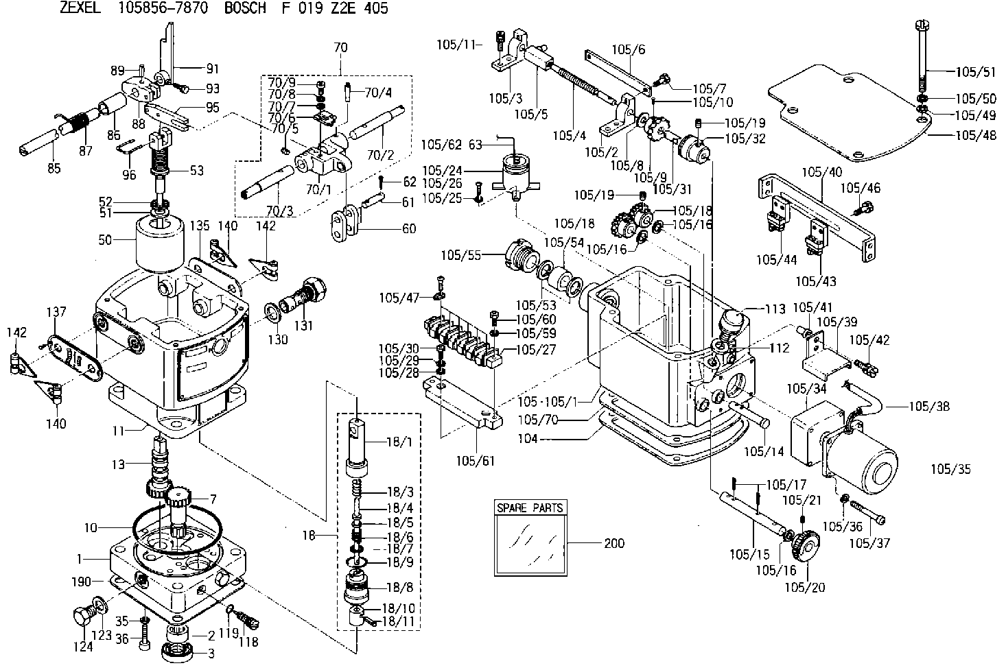
F 019 Z2E 405
f019z2e405
ZEXEL
105856-7870
1058567870
NIIGATA-TEKKOU
74044151A
74044151a
Rating:
Components :
| 0. | INJECTION-PUMP ASSEMBLY | 105856-7870 |
| 1. | _ | |
| 2. | FUEL INJECTION PUMP | |
| 3. | NUMBER PLATE | |
| 4. | _ | |
| 5. | CAPSULE | |
| 6. | ADJUSTING DEVICE | |
| 7. | NOZZLE AND HOLDER ASSY | |
| 8. | Nozzle and Holder | |
| 9. | Open Pre:MPa(Kqf/cm2) | |
| 10. | NOZZLE-HOLDER | |
| 11. | NOZZLE |
Scheme ###:
| 1. | [1] | 158502-0420 | BASE |
| 2. | [1] | 029811-8000 | BEARING PLATE |
| 3. | [1] | 158528-0900 | PACKING RING |
| 7. | [1] | 158131-0100 | GEAR SHAFT |
| 10. | [1] | 158028-0000 | O-RING |
| 11. | [1] | 158507-1820 | DIAPHRAGM HOUSING |
| 13. | [1] | 158621-0500 | SLEEVE |
| 18. | [1] | 158699-0321 | COMPENSATOR ASSY |
| 18/1. | [1] | 158610-0901 | POWER PISTON |
| 18/3. | [1] | 158654-0400 | COILED SPRING |
| 18/4. | [1] | 158614-0300 | STOP PIN |
| 18/5. | [1] | 158612-0500 | PLAIN WASHER |
| 18/6. | [1] | 158654-0500 | COILED SPRING |
| 18/7. | [1] | 016110-1220 | LOCKING WASHER |
| 18/8. | [1] | 158612-0001 | BUSHING |
| 18/9. | [2] | 158528-1300 | O-RING |
| 18/10. | [1] | 158615-0300 | PUMP PLUNGER |
| 18/11. | [1] | 025620-1410 | SPRING PIN |
| 35. | [3] | 029330-6070 | GASKET |
| 36. | [3] | 010206-2520 | HEX-SOCKET-HEAD CAP SCREW |
| 50. | [1] | 158600-0720 | FLYWEIGHT ASSEMBLY |
| 51. | [1] | 158106-0100 | PLAIN WASHER |
| 52. | [1] | 029811-0000 | BEARING PLATE |
| 53. | [1] | 158620-1120 | PILOT VALVE |
| 60. | [2] | 158220-0000 | GUIDE LEVER |
| 61. | [2] | 158736-0200 | BEARING PIN |
| 62. | [4] | 025520-1510 | SPLIT PIN |
| 70. | [1] | 158730-0220 | TERMINAL ARM |
| 70/1. | [1] | 158230-0020 | TERMINAL ARM |
| 70/2. | [1] | 158315-0200 | TERMINAL SHAFT |
| 70/3. | [1] | 158315-0200 | TERMINAL SHAFT |
| 70/4. | [2] | 158736-0100 | TAPER PIN |
| 70/5. | [2] | 011006-0620 | SET OF NUTS |
| 70/6. | [1] | 158214-0020 | SPEED DROOP ADJUSTER |
| 70/7. | [1] | 014020-5120 | PLAIN WASHER |
| 70/8. | [1] | 029320-5030 | TAB WASHER |
| 70/9. | [1] | 010535-1220 | FLAT-HEAD SCREW |
| 85. | [1] | 158814-1200 | SPEED CONTROL SHAFT |
| 86. | [1] | 158823-0300 | BUSHING |
| 87. | [1] | 158322-0200 | COILED SPRING |
| 88. | [1] | 158710-0400 | STRAP |
| 89. | [1] | 029404-5010 | BEARING PIN |
| 91. | [1] | 158712-2000 | CONTROL LEVER |
| 93. | [1] | 029010-5210 | BLEEDER SCREW |
| 95. | [1] | 158211-0100 | STRAP |
| 96. | [2] | 158653-0100 | WIRE |
| 104. | [1] | 158017-0900 | GASKET |
| 105. | [1] | 158964-7920 | GOVERNOR MOTOR ASSY |
| 105/1. | [1] | 158962-5210 | CASE |
| 105/2. | [1] | 158903-0200 | HOLDER |
| 105/3. | [1] | 158903-0300 | HOLDER |
| 105/4. | [1] | 158903-0400 | FLAT-HEAD SCREW |
| 105/5. | [1] | 158903-1720 | ADJUSTER |
| 105/6. | [2] | 158903-0800 | PLATE |
| 105/7. | [4] | 029010-6330 | BLEEDER SCREW M6P1.0L13 |
| 105/8. | [1] | 014020-8140 | PLAIN WASHER D16&8.5T1.2 |
| 105/9. | [1] | 158904-0500 | TOOTHED GEAR |
| 105/10. | [1] | 158590-0000 | BEARING PIN |
| 105/11. | [2] | 020106-1640 | BLEEDER SCREW M6P1.0L14 |
| 105/14. | [1] | 158904-0300 | LEVER SHAFT |
| 105/15. | [1] | 158904-0200 | LEVER SHAFT |
| 105/16. | [3] | 014020-8140 | PLAIN WASHER D16&8.5T1.2 |
| 105/16. | [3] | 014020-8140 | PLAIN WASHER D16&8.5T1.2 |
| 105/16. | [3] | 014020-8140 | PLAIN WASHER D16&8.5T1.2 |
| 105/17. | [3] | 015320-1540 | SPLIT PIN |
| 105/18. | [2] | 158904-0400 | TOOTHED GEAR |
| 105/18. | [2] | 158904-0400 | TOOTHED GEAR |
| 105/19. | [3] | 011005-0820 | SET OF NUTS |
| 105/19. | [3] | 011005-0820 | SET OF NUTS |
| 105/20. | [1] | 158904-1920 | ROUND NUT |
| 105/21. | [1] | 158916-0000 | SET OF NUTS |
| 105/24. | [1] | 158908-3900 | CONDENSER |
| 105/25. | [2] | 014110-3440 | LOCKING WASHER |
| 105/26. | [2] | 012153-0840 | FLAT-HEAD SCREW M3P0.5L8 |
| 105/27. | [1] | 158906-1500 | TERMINAL BOARD |
| 105/28. | [2] | 014020-4140 | PLAIN WASHER D8&4.5T0.5 |
| 105/29. | [2] | 014110-4440 | LOCKING WASHER |
| 105/30. | [2] | 012154-1040 | FLAT-HEAD SCREW M4P0.7L10 |
| 105/31. | [1] | 158902-0300 | JOINT CONNECTION |
| 105/32. | [1] | 158902-0020 | FRICTION COUPLING |
| 105/34. | [1] | 158908-3400 | GEAR HEAD |
| 105/35. | [1] | 158908-4200 | MOTOR |
| 105/36. | [4] | 014020-4140 | PLAIN WASHER D8&4.5T0.5 |
| 105/37. | [4] | 158901-8100 | FLAT-HEAD SCREW |
| 105/38. | [1] | 158901-9700 | HOSE |
| 105/39. | [1] | 158901-8300 | COVER |
| 105/40. | [1] | 158900-0300 | BRACKET |
| 105/41. | [3] | 158900-0200 | BUSHING |
| 105/42. | [3] | 029010-6350 | BLEEDER SCREW M6P1.0L22 |
| 105/43. | [1] | 158907-3820 | LIMIT SWITCH |
| 105/44. | [1] | 158907-3720 | LIMIT SWITCH |
| 105/46. | [2] | 020144-1240 | BLEEDER SCREW |
| 105/47. | [5] | 158906-0801 | TERMINAL |
| 105/48. | [1] | 158562-2600 | COVER |
| 105/49. | [4] | 014020-6140 | PLAIN WASHER |
| 105/50. | [4] | 014110-6440 | LOCKING WASHER |
| 105/51. | [4] | 158909-0100 | BLEEDER SCREW |
| 105/53. | [2] | 158901-2700 | PLAIN WASHER |
| 105/54. | [1] | 158901-2800 | PACKING |
| 105/55. | [1] | 158901-2600 | GROUND |
| 105/59. | [2] | 014110-4440 | LOCKING WASHER |
| 105/60. | [2] | 012154-1640 | FLAT-HEAD SCREW |
| 105/61. | [1] | 158906-1600 | SPACER BUSHING |
| 105/62. | [1] | 158901-2000 | WIRE |
| 105/63. | [1] | 158901-1800 | WIRE |
| 105/70. | [1] | 158563-1300 | COVER |
| 112. | [1] | 026512-1640 | GASKET D15.9&12.2T1 |
| 113. | [1] | 155406-0220 | AIR FILTER |
| 118. | [1] | 158027-0100 | NEEDLE VALVE |
| 119. | [1] | 016500-0710 | O-RING |
| 123. | [2] | 026512-1640 | GASKET D15.9&12.2T1 |
| 124. | [2] | 029111-2070 | CAPSULE M12P1.5L10 |
| 130. | [1] | 029331-8040 | GASKET |
| 131. | [1] | 158660-0020 | CONTROL VALVE |
| 135. | [1] | 158515-0700 | INDICATOR PLATE |
| 137. | [1] | 158515-0800 | INDICATOR PLATE |
| 140. | [2] | 158820-0620 | POINTER |
| 140. | [2] | 158820-0620 | POINTER |
| 142. | [2] | 158820-0620 | POINTER |
| 142. | [2] | 158820-0620 | POINTER |
| 190. | [1] | 158017-1000 | GASKET |
| 200. | [1] | 158599-6720 | SPARE PART |
Include in #2:
105856-7870
as INJECTION-PUMP ASSEMBLY
Cross reference number
Zexel num
Bosch num
Firm num
Name
Information:
Start By:a. remove valve covers 1. Use tooling (A), and disconnect fuel line (1) at each end. Remove the fuel line from the engine. 2. Use tool (B), and remove retainer (2) from the adapter.3. Remove the fuel injection nozzles with tooling (C) as follows:a. Install the 6V6983 Adapter and the 8T3199 Screw into nozzle assembly (3).b. Install the 8T3198 Tube over the 8T3199 Screw.c. Use the 1B4206 Nut on the 8T3199 Screw.d. Use the 1B4206 Nut on the 8T3199 Screw to pull the fuel injection nozzle from the adapter.4. Remove compression seal (4) and carbon dam seal (8) from fuel injection nozzle (3).5. Use tool (D), and remove adapter (6) from the cylinder head.6. Remove gasket (7) and seal (5) from adapter (6). The following steps are for installation of the fuel injection nozzles and adapters.7. Use tool (E) to clean the bore in adapter (6). Use an open end wrench or tap driver to turn tool (E).8. Inspect seal (5) for damage or wear. Replace the seal if necessary.9. Put washer (7) and seal (5) in position on adapter (6).10. Put liquid soap in the bores of the cylinder head and on seals (5) in the adapters.11. Put 5P3931 Anti-Seize Compound on the threads of adapter (6), and install the adapter in the cylinder head assembly.12. Use tool (D), and tighten the adapter to a torque of 205 14 N m (150 10 lb.ft.).
Make sure the correct compression seal washer (4) is used when the nozzle assembly is installed in the adapter. Only copper washers are to be used with this adapter.
13. Install compression seal washer (4), and use tool (F) to install carbon dam seal (8) on the fuel injection nozzle.14. Put fuel injection nozzle (3) in position in the adapter, and install retainer (2).15. Use tool (B) to tighten retainer (2) to a torque of 48 7 N m (35 5 lb.ft.).16. Install fuel line (1). Tighten the nuts on the fuel line with tooling (A) to a torque of 40 7 N m (30 5 lb.ft.).End By:a. install valve covers