Information hydraulic governor
BOSCH
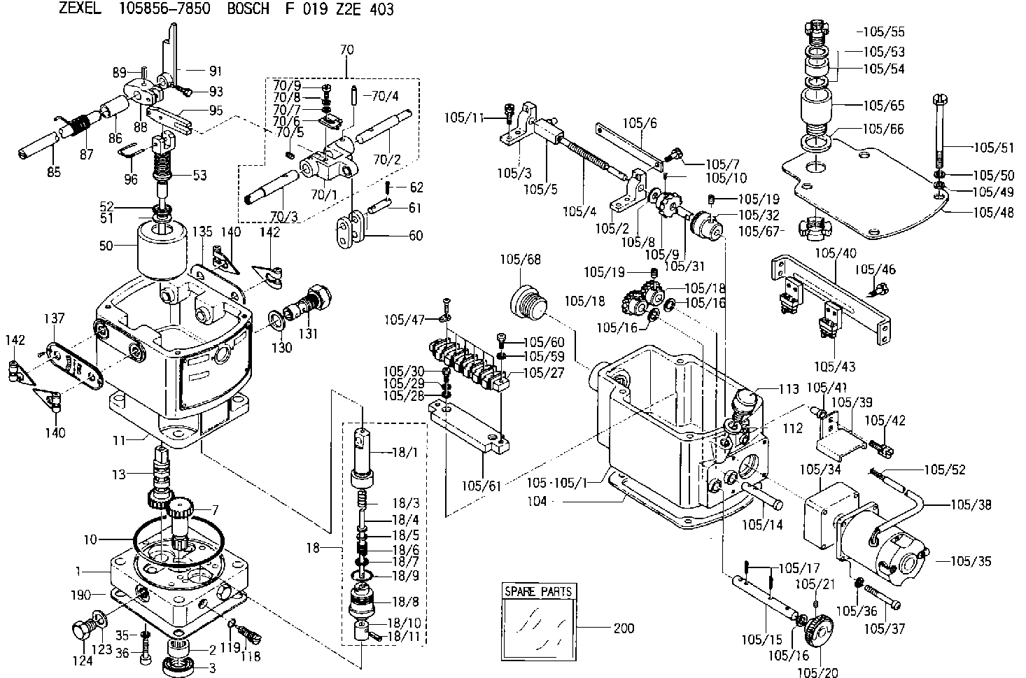
F 019 Z2E 403
f019z2e403
ZEXEL
105856-7850
1058567850
Rating:
Components :
| 0. | INJECTION-PUMP ASSEMBLY | 105856-7850 |
| 1. | _ | |
| 2. | FUEL INJECTION PUMP | |
| 3. | NUMBER PLATE | |
| 4. | _ | |
| 5. | CAPSULE | |
| 6. | ADJUSTING DEVICE | |
| 7. | NOZZLE AND HOLDER ASSY | |
| 8. | Nozzle and Holder | |
| 9. | Open Pre:MPa(Kqf/cm2) | |
| 10. | NOZZLE-HOLDER | |
| 11. | NOZZLE |
Scheme ###:
| 1. | [1] | 158502-0420 | BASE |
| 2. | [1] | 029811-8000 | BEARING PLATE |
| 3. | [1] | 158528-0900 | PACKING RING |
| 7. | [1] | 158131-0100 | GEAR SHAFT |
| 10. | [1] | 158028-0000 | O-RING |
| 11. | [1] | 158507-1820 | DIAPHRAGM HOUSING |
| 13. | [1] | 158621-0500 | SLEEVE |
| 18. | [1] | 158699-0521 | COMPENSATOR ASSY |
| 18/1. | [1] | 158610-0901 | POWER PISTON |
| 18/3. | [1] | 158654-1000 | COILED SPRING |
| 18/4. | [1] | 158614-0300 | STOP PIN |
| 18/5. | [1] | 158612-0500 | PLAIN WASHER |
| 18/6. | [1] | 158654-1100 | COILED SPRING |
| 18/7. | [1] | 016110-1220 | LOCKING WASHER |
| 18/8. | [1] | 158612-0001 | BUSHING |
| 18/9. | [2] | 158528-1300 | O-RING |
| 18/10. | [1] | 158615-0400 | PUMP PLUNGER |
| 18/11. | [1] | 025620-1410 | SPRING PIN |
| 35. | [3] | 029330-6070 | GASKET |
| 36. | [3] | 010206-2520 | HEX-SOCKET-HEAD CAP SCREW |
| 50. | [1] | 158600-1020 | FLYWEIGHT ASSEMBLY |
| 51. | [1] | 158106-0100 | PLAIN WASHER |
| 52. | [1] | 029811-0000 | BEARING PLATE |
| 53. | [1] | 158620-1220 | PILOT VALVE |
| 60. | [2] | 158220-0000 | GUIDE LEVER |
| 61. | [2] | 158736-0200 | BEARING PIN |
| 62. | [4] | 025520-1510 | SPLIT PIN |
| 70. | [1] | 158730-0220 | TERMINAL ARM |
| 70/1. | [1] | 158230-0020 | TERMINAL ARM |
| 70/2. | [1] | 158315-0200 | TERMINAL SHAFT |
| 70/3. | [1] | 158315-0200 | TERMINAL SHAFT |
| 70/4. | [2] | 158736-0100 | TAPER PIN |
| 70/5. | [2] | 011006-0620 | SET OF NUTS |
| 70/6. | [1] | 158214-0020 | SPEED DROOP ADJUSTER |
| 70/7. | [1] | 014020-5120 | PLAIN WASHER |
| 70/8. | [1] | 029320-5030 | TAB WASHER |
| 70/9. | [1] | 010535-1220 | FLAT-HEAD SCREW |
| 85. | [1] | 158814-1200 | SPEED CONTROL SHAFT |
| 86. | [1] | 158823-0300 | BUSHING |
| 87. | [1] | 158322-0200 | COILED SPRING |
| 88. | [1] | 158710-0400 | STRAP |
| 89. | [1] | 029404-5010 | BEARING PIN |
| 91. | [1] | 158712-2000 | CONTROL LEVER |
| 93. | [1] | 029010-5210 | BLEEDER SCREW |
| 95. | [1] | 158211-0100 | STRAP |
| 96. | [2] | 158653-0100 | WIRE |
| 104. | [1] | 158017-0900 | GASKET |
| 105. | [1] | 158964-7820 | GOVERNOR MOTOR ASSY |
| 105/1. | [1] | 158962-0410 | CASE |
| 105/2. | [1] | 158903-0200 | HOLDER |
| 105/3. | [1] | 158903-0300 | HOLDER |
| 105/4. | [1] | 158903-0400 | FLAT-HEAD SCREW |
| 105/5. | [1] | 158903-1720 | ADJUSTER |
| 105/6. | [2] | 158903-0800 | PLATE |
| 105/7. | [4] | 029010-6330 | BLEEDER SCREW M6P1.0L13 |
| 105/8. | [1] | 014020-8140 | PLAIN WASHER D16&8.5T1.2 |
| 105/9. | [1] | 158904-0500 | TOOTHED GEAR |
| 105/10. | [1] | 158590-0000 | BEARING PIN |
| 105/11. | [2] | 020106-1640 | BLEEDER SCREW M6P1.0L14 |
| 105/14. | [1] | 158904-0300 | LEVER SHAFT |
| 105/15. | [1] | 158904-0200 | LEVER SHAFT |
| 105/16. | [3] | 014020-8140 | PLAIN WASHER D16&8.5T1.2 |
| 105/16. | [3] | 014020-8140 | PLAIN WASHER D16&8.5T1.2 |
| 105/16. | [3] | 014020-8140 | PLAIN WASHER D16&8.5T1.2 |
| 105/17. | [3] | 015320-1540 | SPLIT PIN |
| 105/18. | [2] | 158904-0400 | TOOTHED GEAR |
| 105/18. | [2] | 158904-0400 | TOOTHED GEAR |
| 105/19. | [3] | 011005-0820 | SET OF NUTS |
| 105/19. | [3] | 011005-0820 | SET OF NUTS |
| 105/20. | [1] | 158904-1920 | ROUND NUT |
| 105/21. | [1] | 158916-0000 | SET OF NUTS |
| 105/27. | [1] | 158906-1900 | TERMINAL BOARD |
| 105/28. | [2] | 014020-4140 | PLAIN WASHER D8&4.5T0.5 |
| 105/29. | [2] | 014110-4440 | LOCKING WASHER |
| 105/30. | [2] | 012154-1040 | FLAT-HEAD SCREW M4P0.7L10 |
| 105/31. | [1] | 158902-0300 | JOINT CONNECTION |
| 105/32. | [1] | 158902-0020 | FRICTION COUPLING |
| 105/34. | [1] | 158908-2800 | GEAR HEAD |
| 105/35. | [1] | 158901-7301 | MOTOR |
| 105/36. | [4] | 014020-4140 | PLAIN WASHER D8&4.5T0.5 |
| 105/37. | [4] | 158901-8100 | FLAT-HEAD SCREW |
| 105/38. | [1] | 158901-2200 | HOSE |
| 105/39. | [1] | 158901-4300 | COVER |
| 105/40. | [1] | 158900-0300 | BRACKET |
| 105/41. | [3] | 158900-0200 | BUSHING |
| 105/42. | [3] | 029010-6350 | BLEEDER SCREW M6P1.0L22 |
| 105/43. | [2] | 158907-2320 | LIMIT SWITCH |
| 105/46. | [4] | 020144-1240 | BLEEDER SCREW |
| 105/47. | [3] | 158906-0801 | TERMINAL |
| 105/48. | [1] | 158962-0300 | COVER |
| 105/49. | [4] | 014020-6140 | PLAIN WASHER |
| 105/50. | [4] | 014110-6440 | LOCKING WASHER |
| 105/51. | [4] | 158909-0100 | BLEEDER SCREW |
| 105/52. | [1] | 158901-4400 | WIRE |
| 105/53. | [2] | 158401-7300 | GASKET |
| 105/54. | [1] | 158401-7500 | GASKET |
| 105/55. | [1] | 158401-7400 | GROUND |
| 105/59. | [2] | 014110-4440 | LOCKING WASHER |
| 105/60. | [2] | 012154-1640 | FLAT-HEAD SCREW |
| 105/61. | [1] | 158906-2000 | SPACER BUSHING |
| 105/65. | [1] | 158901-6200 | ADAPTOR |
| 105/66. | [1] | 158901-6300 | GASKET |
| 105/67. | [1] | 158901-6400 | UNION NUT |
| 105/68. | [1] | 158591-0000 | CAPSULE |
| 112. | [1] | 026512-1640 | GASKET D15.9&12.2T1 |
| 113. | [1] | 155406-0220 | AIR FILTER |
| 118. | [1] | 158527-0200 | NEEDLE VALVE |
| 119. | [1] | 016500-0710 | O-RING |
| 123. | [2] | 026512-1640 | GASKET D15.9&12.2T1 |
| 124. | [2] | 029111-2070 | CAPSULE M12P1.5L10 |
| 130. | [1] | 029331-8040 | GASKET |
| 131. | [1] | 158660-0320 | CONTROL VALVE |
| 135. | [1] | 158515-0700 | INDICATOR PLATE |
| 137. | [1] | 158515-0800 | INDICATOR PLATE |
| 140. | [2] | 158820-0620 | POINTER |
| 140. | [2] | 158820-0620 | POINTER |
| 142. | [2] | 158820-0620 | POINTER |
| 142. | [2] | 158820-0620 | POINTER |
| 190. | [1] | 158017-1000 | GASKET |
| 200. | [1] | 158599-6720 | SPARE PART |
Include in #2:
105856-7850
as INJECTION-PUMP ASSEMBLY
Cross reference number
Zexel num
Bosch num
Firm num
Name
Information:
2. Loosen the clamps on breather tube (1), and pull it back for clearance. 3. Remove bolt (2) from the cover on the side of the cylinder block. 4. Remove the three bolts that hold cover (3) to the water pump. Remove cover (3) from the water pump. 5. Remove two bolts (4), and remove bonnet (5). 6. Remove six bolts (6) that hold the water pump to the timing gear cover. Remove the water pump.7. Check the O-ring seals and gaskets, and make replacements if needed.For the installation of the water pump reverse the removal procedures.8. See Maintenance Manual for coolant refill.End By:a. remove alternator and mounting groupb. remove water temperature regulator and manifoldDisassemble & Assemble Water Pump
Start By:a. remove water pump The water pump seal can be replaced without removing the water pump from the engine.An intermittent leakage of a small amount of coolant from the hole in the water pump housing is not an indication of a water pump seal failure. This is required to provide lubrication for the seal. Replace the water pump seal only if a large amount of leakage or a constant flow of coolant is observed draining from the water pump housing. 1. Remove O-ring seal (3) from adapter (4). Remove the adapter from housing (7). Remove the O-ring seal from the outside of the adapter.2. Remove bolt (1) and washer (2). Use tooling (A) to remove impeller (6) from shaft (13).3. Remove spring and seal (5) from the shaft.4. Remove four bolts (16) from retainer (12) that hold the shaft assembly to the pump housing. Remove O-ring seal (18) from housing (7).5. Remove gear and shaft assembly (17) from the housing. Remove bolt (15), retainer (14), and retainer (12) from the shaft assembly.6. Use a press to remove shaft (13) from the gear. Remove bearing (9), spacer (10), and bearing (11) from the shaft.7. Remove lip-type seal (8) from the housing.8. Turn the housing over, and remove ceramic ring (20) and seal (19) from the housing. The following steps are for the assembly of the water pump.9. Use 6V1541 Quick Cure Primer and clean shaft (13) and the seal counter bore in the pump housing.10. Install bearing (9), spacer (10), and bearing (11) on shaft (13).11. Put retainer (12) and gear (17) on the shaft assembly. Install retainer (14) and bolt (15) on the shaft.12. Use tooling (B) to install lip-type seal (8) in housing (7). Install seal with the lip toward the inside of the housing. Put a small amount of clean engine oil on the lip of the seal.13. Install a new O-ring seal (18) on the housing.14. Put gear and shaft assembly (17) in position in the housing. Install bolts (16) that hold retainer (12) to the housing.
Clean water only is permitted for use as a lubricant for assistance at installation. Do not damage or put hands on the wear surface of the carbon ring or the ceramic ring. Install the ceramic ring with the smoothest face