Information hydraulic governor
BOSCH
F 019 Z1F 218
f019z1f218
ZEXEL
105856-7841
1058567841
Rating:
Components :
| 0. | INJECTION-PUMP ASSEMBLY | 105856-7841 |
| 1. | _ | |
| 2. | FUEL INJECTION PUMP | |
| 3. | NUMBER PLATE | |
| 4. | _ | |
| 5. | CAPSULE | |
| 6. | ADJUSTING DEVICE | |
| 7. | NOZZLE AND HOLDER ASSY | |
| 8. | Nozzle and Holder | |
| 9. | Open Pre:MPa(Kqf/cm2) | |
| 10. | NOZZLE-HOLDER | |
| 11. | NOZZLE |
Scheme ###:
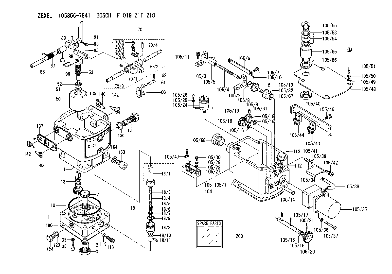
| 1. | [1] | 158502-0420 | BASE |
| 2. | [1] | 029811-8000 | BEARING PLATE |
| 3. | [1] | 158528-0900 | PACKING RING |
| 7. | [1] | 158131-0100 | GEAR SHAFT |
| 10. | [1] | 158028-0000 | O-RING |
| 11. | [1] | 158507-1120 | DIAPHRAGM HOUSING |
| 13. | [1] | 158621-0500 | SLEEVE |
| 18. | [1] | 158699-0521 | COMPENSATOR ASSY |
| 18/1. | [1] | 158610-0901 | POWER PISTON |
| 18/3. | [1] | 158654-1000 | COILED SPRING |
| 18/4. | [1] | 158614-0300 | STOP PIN |
| 18/5. | [1] | 158612-0500 | PLAIN WASHER |
| 18/6. | [1] | 158654-1100 | COILED SPRING |
| 18/7. | [1] | 016110-1220 | LOCKING WASHER |
| 18/8. | [1] | 158612-0001 | BUSHING |
| 18/9. | [2] | 158528-1300 | O-RING |
| 18/10. | [1] | 158615-0400 | PUMP PLUNGER |
| 18/11. | [1] | 025620-1410 | SPRING PIN |
| 35. | [3] | 029330-6070 | GASKET |
| 36. | [3] | 010206-2520 | HEX-SOCKET-HEAD CAP SCREW |
| 50. | [1] | 158600-1020 | FLYWEIGHT ASSEMBLY |
| 51. | [1] | 158106-0100 | PLAIN WASHER |
| 52. | [1] | 029811-0000 | BEARING PLATE |
| 53. | [1] | 158620-1220 | PILOT VALVE |
| 60. | [2] | 158220-0000 | GUIDE LEVER |
| 61. | [2] | 158736-0200 | BEARING PIN |
| 62. | [4] | 025520-1510 | SPLIT PIN |
| 70. | [1] | 158730-0220 | TERMINAL ARM |
| 70/1. | [1] | 158230-0020 | TERMINAL ARM |
| 70/2. | [1] | 158315-0200 | TERMINAL SHAFT |
| 70/3. | [1] | 158315-0200 | TERMINAL SHAFT |
| 70/4. | [2] | 158736-0100 | TAPER PIN |
| 70/5. | [2] | 011006-0620 | SET OF NUTS |
| 70/6. | [1] | 158214-0020 | SPEED DROOP ADJUSTER |
| 70/7. | [1] | 014020-5120 | PLAIN WASHER |
| 70/8. | [1] | 029320-5030 | TAB WASHER |
| 70/9. | [1] | 010535-1220 | FLAT-HEAD SCREW |
| 85. | [1] | 158814-1200 | SPEED CONTROL SHAFT |
| 86. | [1] | 158823-0300 | BUSHING |
| 87. | [1] | 158322-0200 | COILED SPRING |
| 88. | [1] | 158710-0400 | STRAP |
| 89. | [1] | 029404-5010 | BEARING PIN |
| 91. | [1] | 158712-2000 | CONTROL LEVER |
| 93. | [1] | 029010-5210 | BLEEDER SCREW |
| 95. | [1] | 158211-0100 | STRAP |
| 96. | [2] | 158653-0100 | WIRE |
| 104. | [1] | 158017-0900 | GASKET |
| 105. | [1] | 158964-7721 | GOVERNOR MOTOR ASSY |
| 105/1. | [1] | 158962-0410 | CASE |
| 105/2. | [1] | 158903-0200 | HOLDER |
| 105/3. | [1] | 158903-0300 | HOLDER |
| 105/4. | [1] | 158903-0400 | FLAT-HEAD SCREW |
| 105/5. | [1] | 158903-1720 | ADJUSTER |
| 105/6. | [2] | 158903-0800 | PLATE |
| 105/7. | [4] | 029010-6330 | BLEEDER SCREW M6P1.0L13 |
| 105/8. | [1] | 014020-8140 | PLAIN WASHER D16&8.5T1.2 |
| 105/9. | [1] | 158904-0500 | TOOTHED GEAR |
| 105/10. | [1] | 158590-0000 | BEARING PIN |
| 105/11. | [2] | 020106-1640 | BLEEDER SCREW M6P1.0L14 |
| 105/14. | [1] | 158904-0300 | LEVER SHAFT |
| 105/15. | [1] | 158904-0200 | LEVER SHAFT |
| 105/16. | [3] | 014020-8140 | PLAIN WASHER D16&8.5T1.2 |
| 105/16. | [3] | 014020-8140 | PLAIN WASHER D16&8.5T1.2 |
| 105/16. | [3] | 014020-8140 | PLAIN WASHER D16&8.5T1.2 |
| 105/17. | [3] | 015320-1540 | SPLIT PIN |
| 105/18. | [2] | 158904-0400 | TOOTHED GEAR |
| 105/18. | [2] | 158904-0400 | TOOTHED GEAR |
| 105/19. | [3] | 011005-0820 | SET OF NUTS |
| 105/19. | [3] | 011005-0820 | SET OF NUTS |
| 105/20. | [1] | 158904-1920 | ROUND NUT |
| 105/21. | [1] | 158916-0000 | SET OF NUTS |
| 105/24. | [1] | 158908-3900 | CONDENSER |
| 105/25. | [2] | 014110-3440 | LOCKING WASHER |
| 105/26. | [2] | 012153-0840 | FLAT-HEAD SCREW M3P0.5L8 |
| 105/27. | [1] | 158906-0700 | TERMINAL BOARD |
| 105/28. | [2] | 014020-4140 | PLAIN WASHER D8&4.5T0.5 |
| 105/29. | [2] | 014110-4440 | LOCKING WASHER |
| 105/30. | [2] | 012154-1640 | FLAT-HEAD SCREW |
| 105/31. | [1] | 158902-0300 | JOINT CONNECTION |
| 105/32. | [1] | 158902-0020 | FRICTION COUPLING |
| 105/34. | [1] | 158908-5800 | GEAR HEAD |
| 105/35. | [1] | 158908-5020 | MOTOR |
| 105/36. | [4] | 014020-4140 | PLAIN WASHER D8&4.5T0.5 |
| 105/37. | [4] | 158901-8100 | FLAT-HEAD SCREW |
| 105/38. | [1] | 158901-2200 | HOSE |
| 105/39. | [1] | 158901-8300 | COVER |
| 105/40. | [1] | 158900-0300 | BRACKET |
| 105/41. | [3] | 158900-0200 | BUSHING |
| 105/42. | [3] | 029010-6350 | BLEEDER SCREW M6P1.0L22 |
| 105/43. | [1] | 158907-1820 | LIMIT SWITCH |
| 105/44. | [1] | 158907-1720 | LIMIT SWITCH |
| 105/46. | [4] | 020144-1240 | BLEEDER SCREW |
| 105/47. | [1] | 158906-0801 | TERMINAL |
| 105/48. | [1] | 158962-0300 | COVER |
| 105/49. | [4] | 014020-6140 | PLAIN WASHER |
| 105/50. | [4] | 014110-6440 | LOCKING WASHER |
| 105/51. | [4] | 158909-0100 | BLEEDER SCREW |
| 105/53. | [2] | 158401-7300 | GASKET |
| 105/54. | [1] | 158401-7500 | GASKET |
| 105/55. | [1] | 158401-7400 | GROUND |
| 105/65. | [1] | 158901-6200 | ADAPTOR |
| 105/66. | [1] | 158901-6300 | GASKET |
| 105/67. | [1] | 158901-6400 | UNION NUT |
| 105/68. | [1] | 158591-0000 | CAPSULE |
| 112. | [1] | 026512-1640 | GASKET D15.9&12.2T1 |
| 113. | [1] | 155406-0220 | AIR FILTER |
| 118. | [1] | 158527-0200 | NEEDLE VALVE |
| 119. | [1] | 016500-0710 | O-RING |
| 123. | [2] | 026512-1640 | GASKET D15.9&12.2T1 |
| 124. | [2] | 029111-2070 | CAPSULE M12P1.5L10 |
| 130. | [1] | 029331-8040 | GASKET |
| 131. | [1] | 158660-0320 | CONTROL VALVE |
| 135. | [1] | 158515-0700 | INDICATOR PLATE |
| 137. | [1] | 158515-0800 | INDICATOR PLATE |
| 140. | [2] | 158820-0620 | POINTER |
| 140. | [2] | 158820-0620 | POINTER |
| 142. | [2] | 158820-0620 | POINTER |
| 142. | [2] | 158820-0620 | POINTER |
| 163. | [1] | 010210-1420 | HEX-SOCKET-HEAD CAP SCREW |
| 164. | [1] | 026510-1340 | GASKET D13.4&10.2T1 |
| 190. | [1] | 158017-1000 | GASKET |
| 200. | [1] | 158599-6720 | SPARE PART |
Include in #2:
105856-7841
as INJECTION-PUMP ASSEMBLY
Cross reference number
Zexel num
Bosch num
Firm num
Name
Information:
1. Fasten straps and a hoist to the turbocharger.2. Disconnect tube assemblies (1) and (4) from the turbocharger cartridge assembly.3. Remove four bolts (3) and then remove turbocharger (2). Weight of the turbocharger is 23 kg (51 lb.). The following steps are for the installation of the turbocharger.4. Put turbocharger (2) in position with bolts (3).5. Connect tube assemblies (1) and (4) to the turbocharger cartridge assembly.Disassemble Turbocharger
Start By:a. remove turbocharger 1. Install the turbocharger in tool group (A). Put alignment marks on the three housings of the turbocharger for correct installation and alignment at assembly. Remove "V" clamp (2) and compressor housing (1). 2. Remove "V" clamp (3). Remove cartridge housing (5) from turbine housing (4).
When the nut is loosened, do not put a side force on the shaft. This can result in a bent shaft.
3. Install tool (C) in tool (B), and put the cartridge assembly in tool (C) as shown. Use tool (D) to remove the nut that holds compressor wheel (6). 4. Put the cartridge assembly in tool (E), and use a press (if necessary) to remove compressor wheel (6) from the turbine wheel and shaft assembly. Do not let the turbine wheel and shaft assembly fall during removal of the compressor wheel from the turbine wheel and shaft. 5. Remove seal ring (7) and shroud (8) from turbine wheel and shaft assembly (9). 6. Bend the tabs of the locks from bolts (10), and remove the bolts and locks.7. Remove backplate assembly (11) from the cartridge housing. 8. Remove spacer (12) from backplate assembly (11). Remove seal rings (13) from spacer (12). 9. Remove collar (14), thrust bearing (15) and O-ring seal (16) from the cartridge housing. 10. Remove top bearing (17) and the washer from the cartridge housing. Put a long dye mark on the top face of bearing (17).11. Use tool (F), and remove the two rings that hold the top and bottom bearings in position. Remove the bottom bearings and washer. Put a short dye mark on the bearing. The dye marks are used for identification of the bearings when they are installed.12. Use tool (F), and remove the last ring that holds the bottom bearing in position from the cartridge housing.13. Check all the parts of the turbocharger for damage. If the parts are damaged, use new parts for replacement. See Special Instruction Form No. SMHS6854 for Turbocharger Reconditioning. Also see Guidelines For Reusable Parts, Form No. SEBF8018.Assemble Turbocharger
1. Make sure that all of the oil passages in the turbocharger cartridge housing are clean and free of dirt and foreign material.2. Put clean engine oil on all parts of the cartridge assembly.
Rings (18), (21) and (22) must be installed with the round edge of the outside diameter of the rings toward the bearings.
3. Install ring (21) in the cartridge housing with tool (F).4. Install washer (19) and bearing (20) in the cartridge housing. Make sure the short dye mark on bearing (20) is up. 5. Install rings (18) and