Information hydraulic governor
BOSCH
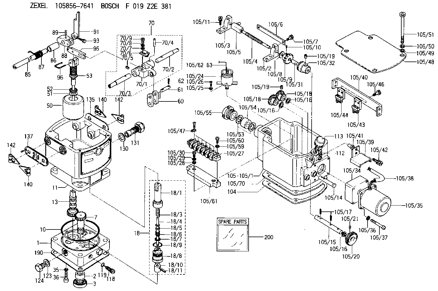
F 019 Z2E 381
f019z2e381
ZEXEL
105856-7641
1058567641
NIIGATA-URAWA
W4044023F
w4044023f
Rating:
Components :
| 0. | INJECTION-PUMP ASSEMBLY | 105856-7641 |
| 1. | _ | |
| 2. | FUEL INJECTION PUMP | |
| 3. | NUMBER PLATE | |
| 4. | _ | |
| 5. | CAPSULE | |
| 6. | ADJUSTING DEVICE | |
| 7. | NOZZLE AND HOLDER ASSY | |
| 8. | Nozzle and Holder | |
| 9. | Open Pre:MPa(Kqf/cm2) | |
| 10. | NOZZLE-HOLDER | |
| 11. | NOZZLE |
Scheme ###:
| 1. | [1] | 158502-0420 | BASE |
| 2. | [1] | 029811-8000 | BEARING PLATE |
| 3. | [1] | 158528-0900 | PACKING RING |
| 7. | [1] | 158131-0100 | GEAR SHAFT |
| 10. | [1] | 158028-0000 | O-RING |
| 11. | [1] | 158507-1820 | DIAPHRAGM HOUSING |
| 13. | [1] | 158621-0500 | SLEEVE |
| 18. | [1] | 158699-0321 | COMPENSATOR ASSY |
| 18/1. | [1] | 158610-0901 | POWER PISTON |
| 18/3. | [1] | 158654-0400 | COILED SPRING |
| 18/4. | [1] | 158614-0300 | STOP PIN |
| 18/5. | [1] | 158612-0500 | PLAIN WASHER |
| 18/6. | [1] | 158654-0500 | COILED SPRING |
| 18/7. | [1] | 016110-1220 | LOCKING WASHER |
| 18/8. | [1] | 158612-0001 | BUSHING |
| 18/9. | [2] | 158528-1300 | O-RING |
| 18/10. | [1] | 158615-0300 | PUMP PLUNGER |
| 18/11. | [1] | 025620-1410 | SPRING PIN |
| 35. | [3] | 029330-6070 | GASKET |
| 36. | [3] | 010206-2520 | HEX-SOCKET-HEAD CAP SCREW |
| 50. | [1] | 158600-0720 | FLYWEIGHT ASSEMBLY |
| 51. | [1] | 158106-0100 | PLAIN WASHER |
| 52. | [1] | 029811-0000 | BEARING PLATE |
| 53. | [1] | 158620-1120 | PILOT VALVE |
| 60. | [2] | 158220-0000 | GUIDE LEVER |
| 61. | [2] | 158736-0200 | BEARING PIN |
| 62. | [4] | 025520-1510 | SPLIT PIN |
| 70. | [1] | 158730-0220 | TERMINAL ARM |
| 70/1. | [1] | 158230-0020 | TERMINAL ARM |
| 70/2. | [1] | 158315-0200 | TERMINAL SHAFT |
| 70/3. | [1] | 158315-0200 | TERMINAL SHAFT |
| 70/4. | [2] | 158736-0100 | TAPER PIN |
| 70/5. | [2] | 011006-0620 | SET OF NUTS |
| 70/6. | [1] | 158214-0020 | SPEED DROOP ADJUSTER |
| 70/7. | [1] | 014020-5120 | PLAIN WASHER |
| 70/8. | [1] | 029320-5030 | TAB WASHER |
| 70/9. | [1] | 010535-1220 | FLAT-HEAD SCREW |
| 85. | [1] | 158814-1200 | SPEED CONTROL SHAFT |
| 86. | [1] | 158823-0300 | BUSHING |
| 87. | [1] | 158322-0200 | COILED SPRING |
| 88. | [1] | 158710-0400 | STRAP |
| 89. | [1] | 029404-5010 | BEARING PIN |
| 91. | [1] | 158712-2000 | CONTROL LEVER |
| 93. | [1] | 029010-5210 | BLEEDER SCREW |
| 95. | [1] | 158211-0100 | STRAP |
| 96. | [2] | 158653-0100 | WIRE |
| 104. | [1] | 158017-0900 | GASKET |
| 105. | [1] | 158964-5021 | GOVERNOR MOTOR ASSY |
| 105/1. | [1] | 158962-5210 | CASE |
| 105/2. | [1] | 158903-0200 | HOLDER |
| 105/3. | [1] | 158903-0300 | HOLDER |
| 105/4. | [1] | 158903-0400 | FLAT-HEAD SCREW |
| 105/5. | [1] | 158903-1720 | ADJUSTER |
| 105/6. | [2] | 158903-0800 | PLATE |
| 105/7. | [4] | 029010-6330 | BLEEDER SCREW M6P1.0L13 |
| 105/8. | [1] | 014020-8140 | PLAIN WASHER D16&8.5T1.2 |
| 105/9. | [1] | 158904-0500 | TOOTHED GEAR |
| 105/10. | [1] | 158590-0000 | BEARING PIN |
| 105/11. | [2] | 020106-1640 | BLEEDER SCREW M6P1.0L14 |
| 105/14. | [1] | 158904-0300 | LEVER SHAFT |
| 105/15. | [1] | 158904-0200 | LEVER SHAFT |
| 105/16. | [3] | 014020-8140 | PLAIN WASHER D16&8.5T1.2 |
| 105/16. | [3] | 014020-8140 | PLAIN WASHER D16&8.5T1.2 |
| 105/16. | [3] | 014020-8140 | PLAIN WASHER D16&8.5T1.2 |
| 105/17. | [3] | 015320-1540 | SPLIT PIN |
| 105/18. | [2] | 158904-0400 | TOOTHED GEAR |
| 105/18. | [2] | 158904-0400 | TOOTHED GEAR |
| 105/19. | [3] | 011005-0820 | SET OF NUTS |
| 105/19. | [3] | 011005-0820 | SET OF NUTS |
| 105/20. | [1] | 158904-1920 | ROUND NUT |
| 105/21. | [1] | 158916-0000 | SET OF NUTS |
| 105/24. | [1] | 158908-3900 | CONDENSER |
| 105/25. | [2] | 014110-3440 | LOCKING WASHER |
| 105/26. | [2] | 012153-0840 | FLAT-HEAD SCREW M3P0.5L8 |
| 105/27. | [1] | 158906-1500 | TERMINAL BOARD |
| 105/28. | [2] | 014020-4140 | PLAIN WASHER D8&4.5T0.5 |
| 105/29. | [2] | 014110-4440 | LOCKING WASHER |
| 105/30. | [2] | 012154-1040 | FLAT-HEAD SCREW M4P0.7L10 |
| 105/31. | [1] | 158902-0300 | JOINT CONNECTION |
| 105/32. | [1] | 158902-0420 | FRICTION COUPLING |
| 105/34. | [1] | 158908-2700 | GEAR HEAD |
| 105/35. | [1] | 158908-4200 | MOTOR |
| 105/36. | [4] | 014020-4140 | PLAIN WASHER D8&4.5T0.5 |
| 105/37. | [4] | 158901-8100 | FLAT-HEAD SCREW |
| 105/38. | [1] | 158901-9700 | HOSE |
| 105/39. | [1] | 158901-8300 | COVER |
| 105/40. | [1] | 158900-0300 | BRACKET |
| 105/41. | [3] | 158900-0200 | BUSHING |
| 105/42. | [3] | 029010-6350 | BLEEDER SCREW M6P1.0L22 |
| 105/43. | [1] | 158907-3820 | LIMIT SWITCH |
| 105/44. | [1] | 158907-3720 | LIMIT SWITCH |
| 105/46. | [2] | 020144-1240 | BLEEDER SCREW |
| 105/47. | [5] | 158906-0801 | TERMINAL |
| 105/48. | [1] | 158562-2600 | COVER |
| 105/49. | [4] | 014020-6140 | PLAIN WASHER |
| 105/50. | [4] | 014110-6440 | LOCKING WASHER |
| 105/51. | [4] | 158909-0100 | BLEEDER SCREW |
| 105/53. | [2] | 158901-2700 | PLAIN WASHER |
| 105/54. | [1] | 158901-2800 | PACKING |
| 105/55. | [1] | 158901-2600 | GROUND |
| 105/59. | [2] | 014110-4440 | LOCKING WASHER |
| 105/60. | [2] | 012154-1640 | FLAT-HEAD SCREW |
| 105/61. | [1] | 158906-1600 | SPACER BUSHING |
| 105/62. | [1] | 158901-2000 | WIRE |
| 105/63. | [2] | 158901-1800 | WIRE |
| 105/70. | [1] | 158563-1300 | COVER |
| 112. | [1] | 026512-1640 | GASKET D15.9&12.2T1 |
| 113. | [1] | 155406-0220 | AIR FILTER |
| 118. | [1] | 158027-0100 | NEEDLE VALVE |
| 119. | [1] | 016500-0710 | O-RING |
| 123. | [2] | 026512-1640 | GASKET D15.9&12.2T1 |
| 124. | [2] | 029111-2070 | CAPSULE M12P1.5L10 |
| 130. | [1] | 029331-8040 | GASKET |
| 131. | [1] | 158660-0020 | CONTROL VALVE |
| 135. | [1] | 158515-0700 | INDICATOR PLATE |
| 137. | [1] | 158515-0800 | INDICATOR PLATE |
| 140. | [2] | 158820-0620 | POINTER |
| 140. | [2] | 158820-0620 | POINTER |
| 142. | [2] | 158820-0620 | POINTER |
| 142. | [2] | 158820-0620 | POINTER |
| 190. | [1] | 158017-1000 | GASKET |
| 200. | [1] | 158599-6720 | SPARE PART |
Include in #2:
105856-7641
as INJECTION-PUMP ASSEMBLY
Cross reference number
Zexel num
Bosch num
Firm num
Name
Information:
Fuel Injection Line Without Support Bracket Two different fuel injection line arrangements are utilized. One arrangement uses a support bracket, the other does not.
Be sure the fuel injection line clamps are installed in the correct locations. Incorrectly installed clamps may allow the fuel injection lines to vibrate and become damaged. The damaged lines may leak and cause a fire.
(1) Clamp location dimensions are in reference to a vertical line (1) through the center of the number one fuel pump outlet. Align brackets in position to fuel lines such that when the fasteners are tightened no strain will be added to the fuel lines while tightening fasteners.(A) ... 35 3 mm (1.38 .12 in)(B) ... 165 13 mm (6.50 .51 in)(C) ... 187 1 mm (7.36 .04 in)(D) ... 187 3 mm (7.36 .12 in)(E) ... 282 3 mm (11.10 .12 in)(F) ... 314 13 mm (12.36 .51 in)(G) ... 457 3 mm (17.99 .12 in)(H) ... 529 3 mm (17.99 .12 in)Tighten metal-to-metal clamps to a torque of ... 2.3 N m (20 lb in) The 6V4980 Torque Screwdriver Tool Group is available for applying the correct torque. (2) Tighten fuel injection line nuts to ... 42 7 N m (31 5 lb ft)(3) Tighten nuts to ... 14 3 N m (10 2 lb ft)(4) Tighten retainer on adapter to ... 48 7 N m (35 5 lb ft)
Fuel Injection Line With Support Bracket
Be sure the fuel injection line clamps are installed in the correct locations. Incorrectly installed clamps may allow the fuel injection lines to vibrate and become damaged. The damaged lines may leak and cause a fire.
(1) Clamp location dimensions are in reference to a vertical line (1) through the center of the number one fuel pump outlet.Align brackets in position to fuel lines such that when the fasteners are tightened no strain will be added to the fuel lines while tightening fasteners.(A) ... 35 3 mm (1.38 .12 in)(B) ... 165 13 mm (6.50 .51 in)(C) ... 187 1 mm (7.36 .04 in)(D) ... 187 3 mm (7.36 .12 in)(E) ... 282 3 mm (11.10 .12 in)(F) ... 283 3 mm (11.14 .12 in)(G) ... 529 3 mm (17.99 .12 in)Tighten metal-to-metal clamps to a torque of ... 2.3 N m (20 lb in) The 6V4980 Torque Screwdriver Tool Group is available for applying the correct torque. (2) Tighten fuel injection line nuts to ... 42 7 N m (31 5 lb ft)(3) Tighten nuts to ... 14 3 N m (10 2 lb ft)(4) Tighten retainer on adapter to ... 48 7 N m (35 5 lb ft)