Information hydraulic governor
BOSCH
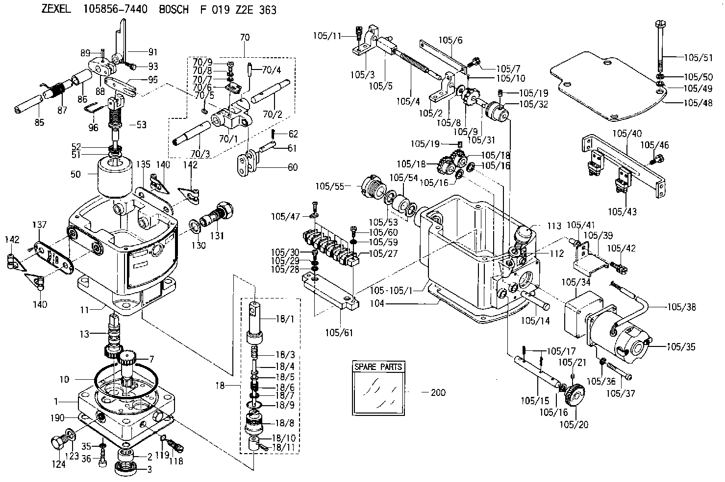
F 019 Z2E 363
f019z2e363
ZEXEL
105856-7440
1058567440
DAIHATSU
QGDK304970FZ
qgdk304970fz
Rating:
Components :
| 0. | INJECTION-PUMP ASSEMBLY | 105856-7440 |
| 1. | _ | |
| 2. | FUEL INJECTION PUMP | |
| 3. | NUMBER PLATE | |
| 4. | _ | |
| 5. | CAPSULE | |
| 6. | ADJUSTING DEVICE | |
| 7. | NOZZLE AND HOLDER ASSY | |
| 8. | Nozzle and Holder | |
| 9. | Open Pre:MPa(Kqf/cm2) | |
| 10. | NOZZLE-HOLDER | |
| 11. | NOZZLE |
Scheme ###:
| 1. | [1] | 158502-0420 | BASE |
| 2. | [1] | 029811-8000 | BEARING PLATE |
| 3. | [1] | 158528-0900 | PACKING RING |
| 7. | [1] | 158131-0100 | GEAR SHAFT |
| 10. | [1] | 158028-0000 | O-RING |
| 11. | [1] | 158507-1820 | DIAPHRAGM HOUSING |
| 13. | [1] | 158621-0800 | SLEEVE |
| 18. | [1] | 158699-0521 | COMPENSATOR ASSY |
| 18/1. | [1] | 158610-0901 | POWER PISTON |
| 18/3. | [1] | 158654-1000 | COILED SPRING |
| 18/4. | [1] | 158614-0300 | STOP PIN |
| 18/5. | [1] | 158612-0500 | PLAIN WASHER |
| 18/6. | [1] | 158654-1100 | COILED SPRING |
| 18/7. | [1] | 016110-1220 | LOCKING WASHER |
| 18/8. | [1] | 158612-0001 | BUSHING |
| 18/9. | [2] | 158528-1300 | O-RING |
| 18/10. | [1] | 158615-0400 | PUMP PLUNGER |
| 18/11. | [1] | 025620-1410 | SPRING PIN |
| 35. | [3] | 029330-6070 | GASKET |
| 36. | [3] | 010206-2520 | HEX-SOCKET-HEAD CAP SCREW |
| 50. | [1] | 158600-1020 | FLYWEIGHT ASSEMBLY |
| 51. | [1] | 158106-0100 | PLAIN WASHER |
| 52. | [1] | 029811-0000 | BEARING PLATE |
| 53. | [1] | 158620-1220 | PILOT VALVE |
| 60. | [2] | 158220-0000 | GUIDE LEVER |
| 61. | [2] | 158736-0200 | BEARING PIN |
| 62. | [4] | 025520-1510 | SPLIT PIN |
| 70. | [1] | 158730-0220 | TERMINAL ARM |
| 70/1. | [1] | 158230-0020 | TERMINAL ARM |
| 70/2. | [1] | 158315-0200 | TERMINAL SHAFT |
| 70/3. | [1] | 158315-0200 | TERMINAL SHAFT |
| 70/4. | [2] | 158736-0100 | TAPER PIN |
| 70/5. | [2] | 011006-0620 | SET OF NUTS |
| 70/6. | [1] | 158214-0020 | SPEED DROOP ADJUSTER |
| 70/7. | [1] | 014020-5120 | PLAIN WASHER |
| 70/8. | [1] | 029320-5030 | TAB WASHER |
| 70/9. | [1] | 010535-1220 | FLAT-HEAD SCREW |
| 85. | [1] | 158814-1200 | SPEED CONTROL SHAFT |
| 86. | [1] | 158823-0300 | BUSHING |
| 87. | [1] | 158322-0200 | COILED SPRING |
| 88. | [1] | 158710-0400 | STRAP |
| 89. | [1] | 029404-5010 | BEARING PIN |
| 91. | [1] | 158712-2000 | CONTROL LEVER |
| 93. | [1] | 029010-5210 | BLEEDER SCREW |
| 95. | [1] | 158211-0100 | STRAP |
| 96. | [2] | 158653-0100 | WIRE |
| 104. | [1] | 158017-0900 | GASKET |
| 105. | [1] | 158964-4120 | GOVERNOR MOTOR ASSY |
| 105/1. | [1] | 158962-5210 | CASE |
| 105/2. | [1] | 158903-0200 | HOLDER |
| 105/3. | [1] | 158903-0300 | HOLDER |
| 105/4. | [1] | 158903-0400 | FLAT-HEAD SCREW |
| 105/5. | [1] | 158903-1720 | ADJUSTER |
| 105/6. | [2] | 158903-0800 | PLATE |
| 105/7. | [4] | 029010-6330 | BLEEDER SCREW M6P1.0L13 |
| 105/8. | [1] | 014020-8140 | PLAIN WASHER D16&8.5T1.2 |
| 105/9. | [1] | 158904-0500 | TOOTHED GEAR |
| 105/10. | [1] | 158590-0000 | BEARING PIN |
| 105/11. | [2] | 020106-1640 | BLEEDER SCREW M6P1.0L14 |
| 105/14. | [1] | 158904-0300 | LEVER SHAFT |
| 105/15. | [1] | 158904-0200 | LEVER SHAFT |
| 105/16. | [3] | 014020-8140 | PLAIN WASHER D16&8.5T1.2 |
| 105/16. | [3] | 014020-8140 | PLAIN WASHER D16&8.5T1.2 |
| 105/16. | [3] | 014020-8140 | PLAIN WASHER D16&8.5T1.2 |
| 105/17. | [3] | 015320-1540 | SPLIT PIN |
| 105/18. | [2] | 158904-0400 | TOOTHED GEAR |
| 105/18. | [2] | 158904-0400 | TOOTHED GEAR |
| 105/19. | [3] | 011005-0820 | SET OF NUTS |
| 105/19. | [3] | 011005-0820 | SET OF NUTS |
| 105/20. | [1] | 158904-1920 | ROUND NUT |
| 105/21. | [1] | 158916-0000 | SET OF NUTS |
| 105/27. | [1] | 158906-1900 | TERMINAL BOARD |
| 105/28. | [2] | 014020-4140 | PLAIN WASHER D8&4.5T0.5 |
| 105/29. | [2] | 014110-4440 | LOCKING WASHER |
| 105/30. | [2] | 012154-1040 | FLAT-HEAD SCREW M4P0.7L10 |
| 105/31. | [1] | 158902-0300 | JOINT CONNECTION |
| 105/32. | [1] | 158902-0020 | FRICTION COUPLING |
| 105/34. | [1] | 158908-3200 | GEAR HEAD |
| 105/35. | [1] | 158901-7301 | MOTOR |
| 105/36. | [4] | 014020-4140 | PLAIN WASHER D8&4.5T0.5 |
| 105/37. | [4] | 158901-8100 | FLAT-HEAD SCREW |
| 105/38. | [1] | 158901-2200 | HOSE |
| 105/39. | [1] | 158901-4300 | COVER |
| 105/40. | [1] | 158900-0300 | BRACKET |
| 105/41. | [3] | 158900-0200 | BUSHING |
| 105/42. | [3] | 029010-6350 | BLEEDER SCREW M6P1.0L22 |
| 105/43. | [2] | 158907-2320 | LIMIT SWITCH |
| 105/46. | [4] | 020144-1240 | BLEEDER SCREW |
| 105/47. | [3] | 158906-0801 | TERMINAL |
| 105/48. | [1] | 158562-2600 | COVER |
| 105/49. | [4] | 014020-6140 | PLAIN WASHER |
| 105/50. | [4] | 014110-6440 | LOCKING WASHER |
| 105/51. | [4] | 158909-0100 | BLEEDER SCREW |
| 105/53. | [2] | 158901-2700 | PLAIN WASHER |
| 105/54. | [1] | 158901-2800 | PACKING |
| 105/55. | [1] | 158901-2600 | GROUND |
| 105/59. | [2] | 014110-4440 | LOCKING WASHER |
| 105/60. | [2] | 012154-1640 | FLAT-HEAD SCREW |
| 105/61. | [1] | 158906-2000 | SPACER BUSHING |
| 112. | [1] | 026512-1640 | GASKET D15.9&12.2T1 |
| 113. | [1] | 155406-0220 | AIR FILTER |
| 118. | [1] | 158527-0200 | NEEDLE VALVE |
| 119. | [1] | 016500-0710 | O-RING |
| 123. | [2] | 026512-1640 | GASKET D15.9&12.2T1 |
| 124. | [2] | 029111-2070 | CAPSULE M12P1.5L10 |
| 130. | [1] | 029331-8040 | GASKET |
| 131. | [1] | 158660-0320 | CONTROL VALVE |
| 135. | [1] | 158515-0700 | INDICATOR PLATE |
| 137. | [1] | 158515-0800 | INDICATOR PLATE |
| 140. | [2] | 158820-0620 | POINTER |
| 140. | [2] | 158820-0620 | POINTER |
| 142. | [2] | 158820-0620 | POINTER |
| 142. | [2] | 158820-0620 | POINTER |
| 190. | [1] | 158017-1000 | GASKET |
| 200. | [1] | 158599-6720 | SPARE PART |
Include in #2:
105856-7440
as INJECTION-PUMP ASSEMBLY
Cross reference number
Zexel num
Bosch num
Firm num
Name
Information:
Engine Runs Smoothly
Possible Causes/Corrections Dirty Air CleanerIf the air cleaner has a restriction indicator, see if the red piston is in view. If there is no restriction indicator, restriction can be checked with a water manometer or a vacuum gauge (which measures in inches of water). Make a connection to the piping between the air cleaner and the inlet of the turbocharger. Check with the engine running at full load rpm. Maximum restriction is 635 mm (25 in) of water. If a gauge is not available, visually check the air cleaner element for dirt. If the element is dirty, clean the element or install a new element. Air Inlet Piping Damage Or RestrictionMake a visual inspection of the air inlet system and check for damage to piping, rags in the inlet piping, or damage to the rain cap or the cap pushed too far on the inlet pipe. If no damage is seen, check inlet restriction with a clean air cleaner element. Exhaust System RestrictionMake a visual inspection of the exhaust system. Check for damage to piping or for a defective muffler. If no damage is found, you can check the system by checking the back pressure from the exhaust (pressure difference measurement between exhaust outlet and atmosphere). The back pressure must not be more than 1016 mm (40 in) of water. You can also check by removing the exhaust pipes from the exhaust manifolds. With the exhaust pipes removed, start and load the engine on a chassis dynamometer to see if the problem is corrected. Fuel Injection Timing Not CorrectCheck and make necessary adjustments as in Testing and Adjusting Section of this Service Manual. Fuel Setting Is Not CorrectCheck and make necessary adjustments as in Testing and Adjusting Section of this Service Manual. See the Fuel Setting And Related Information Fiche for the correct fuel setting. Low Quality FuelTest the engine with fuel according to recommendations by Caterpillar Inc. For more information see Special Instruction, Form No. SEHS7067, Fuel Recommendations For Caterpillar Diesel Engines. Also, Special Instruction, Form No. SEHS6947 has fuel correction factors and tables. Defective Fuel Nozzle(s)Defective fuel nozzles will normally cause the engine to misfire and run rough, but can cause too much smoke with engine still running smooth. Remove the fuel nozzles and test as in Testing and Adjusting Section of this Service Manual. Wrong Seal Washer Installed Under Nozzle(s)The use of incorrect washers change the location of the fuel injection nozzles in the combustion chamber. This effects smoke. Check the Engine Arrangement for the correct part number to use. Valve Adjustment Not Correct Or Valve LeakageCheck and make necessary adjustments as in Testing and Adjusting Section of this Service Manual. Intake valve lash is 0.38 mm (.015 in) and exhaust valve lash is 0.64 mm (.025 in). Valve leakage normally causes the engine to misfire and run rough. Defective Fuel Injection PumpAn injection pump can have a good fuel flow coming from it but cause rough running because of slow timing that
Possible Causes/Corrections Dirty Air CleanerIf the air cleaner has a restriction indicator, see if the red piston is in view. If there is no restriction indicator, restriction can be checked with a water manometer or a vacuum gauge (which measures in inches of water). Make a connection to the piping between the air cleaner and the inlet of the turbocharger. Check with the engine running at full load rpm. Maximum restriction is 635 mm (25 in) of water. If a gauge is not available, visually check the air cleaner element for dirt. If the element is dirty, clean the element or install a new element. Air Inlet Piping Damage Or RestrictionMake a visual inspection of the air inlet system and check for damage to piping, rags in the inlet piping, or damage to the rain cap or the cap pushed too far on the inlet pipe. If no damage is seen, check inlet restriction with a clean air cleaner element. Exhaust System RestrictionMake a visual inspection of the exhaust system. Check for damage to piping or for a defective muffler. If no damage is found, you can check the system by checking the back pressure from the exhaust (pressure difference measurement between exhaust outlet and atmosphere). The back pressure must not be more than 1016 mm (40 in) of water. You can also check by removing the exhaust pipes from the exhaust manifolds. With the exhaust pipes removed, start and load the engine on a chassis dynamometer to see if the problem is corrected. Fuel Injection Timing Not CorrectCheck and make necessary adjustments as in Testing and Adjusting Section of this Service Manual. Fuel Setting Is Not CorrectCheck and make necessary adjustments as in Testing and Adjusting Section of this Service Manual. See the Fuel Setting And Related Information Fiche for the correct fuel setting. Low Quality FuelTest the engine with fuel according to recommendations by Caterpillar Inc. For more information see Special Instruction, Form No. SEHS7067, Fuel Recommendations For Caterpillar Diesel Engines. Also, Special Instruction, Form No. SEHS6947 has fuel correction factors and tables. Defective Fuel Nozzle(s)Defective fuel nozzles will normally cause the engine to misfire and run rough, but can cause too much smoke with engine still running smooth. Remove the fuel nozzles and test as in Testing and Adjusting Section of this Service Manual. Wrong Seal Washer Installed Under Nozzle(s)The use of incorrect washers change the location of the fuel injection nozzles in the combustion chamber. This effects smoke. Check the Engine Arrangement for the correct part number to use. Valve Adjustment Not Correct Or Valve LeakageCheck and make necessary adjustments as in Testing and Adjusting Section of this Service Manual. Intake valve lash is 0.38 mm (.015 in) and exhaust valve lash is 0.64 mm (.025 in). Valve leakage normally causes the engine to misfire and run rough. Defective Fuel Injection PumpAn injection pump can have a good fuel flow coming from it but cause rough running because of slow timing that