Information hydraulic governor
BOSCH
F 019 Z2E 348
f019z2e348
ZEXEL
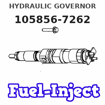
105856-7262
1058567262
AKASAKA-DIESEL
098300120870
098300120870
Rating:
Components :
| 0. | INJECTION-PUMP ASSEMBLY | 105856-7262 |
| 1. | _ | |
| 2. | FUEL INJECTION PUMP | |
| 3. | NUMBER PLATE | |
| 4. | _ | |
| 5. | CAPSULE | |
| 6. | ADJUSTING DEVICE | |
| 7. | NOZZLE AND HOLDER ASSY | |
| 8. | Nozzle and Holder | |
| 9. | Open Pre:MPa(Kqf/cm2) | |
| 10. | NOZZLE-HOLDER | |
| 11. | NOZZLE |
Scheme ###:
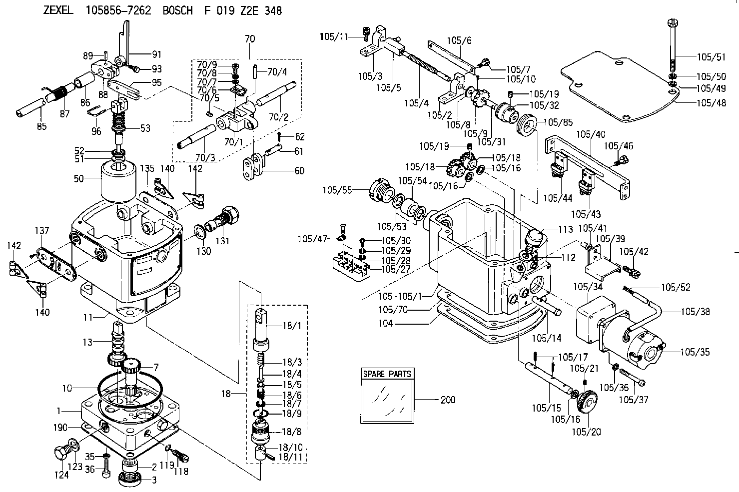
| 1. | [1] | 158502-0420 | BASE |
| 2. | [1] | 029811-8000 | BEARING PLATE |
| 3. | [1] | 158528-0900 | PACKING RING |
| 7. | [1] | 158131-0100 | GEAR SHAFT |
| 10. | [1] | 158028-0000 | O-RING |
| 11. | [1] | 158507-1820 | DIAPHRAGM HOUSING |
| 13. | [1] | 158621-0600 | SLIDING PIECE |
| 18. | [1] | 158699-0521 | COMPENSATOR ASSY |
| 18/1. | [1] | 158610-0901 | POWER PISTON |
| 18/3. | [1] | 158654-1000 | COILED SPRING |
| 18/4. | [1] | 158614-0300 | STOP PIN |
| 18/5. | [1] | 158612-0500 | PLAIN WASHER |
| 18/6. | [1] | 158654-1100 | COILED SPRING |
| 18/7. | [1] | 016110-1220 | LOCKING WASHER |
| 18/8. | [1] | 158612-0001 | BUSHING |
| 18/9. | [2] | 158528-1300 | O-RING |
| 18/10. | [1] | 158615-0400 | PUMP PLUNGER |
| 18/11. | [1] | 025620-1410 | SPRING PIN |
| 35. | [3] | 029330-6070 | GASKET |
| 36. | [3] | 010206-2520 | HEX-SOCKET-HEAD CAP SCREW |
| 50. | [1] | 158600-0720 | FLYWEIGHT ASSEMBLY |
| 51. | [1] | 158106-0100 | PLAIN WASHER |
| 52. | [1] | 029811-0000 | BEARING PLATE |
| 53. | [1] | 158620-1220 | PILOT VALVE |
| 60. | [2] | 158220-0000 | GUIDE LEVER |
| 61. | [2] | 158736-0200 | BEARING PIN |
| 62. | [4] | 025520-1510 | SPLIT PIN |
| 70. | [1] | 158730-0220 | TERMINAL ARM |
| 70/1. | [1] | 158230-0020 | TERMINAL ARM |
| 70/2. | [1] | 158315-0200 | TERMINAL SHAFT |
| 70/3. | [1] | 158315-0200 | TERMINAL SHAFT |
| 70/4. | [2] | 158736-0100 | TAPER PIN |
| 70/5. | [2] | 011006-0620 | SET OF NUTS |
| 70/6. | [1] | 158214-0020 | SPEED DROOP ADJUSTER |
| 70/7. | [1] | 014020-5120 | PLAIN WASHER |
| 70/8. | [1] | 029320-5030 | TAB WASHER |
| 70/9. | [1] | 010535-1220 | FLAT-HEAD SCREW |
| 85. | [1] | 158814-1200 | SPEED CONTROL SHAFT |
| 86. | [1] | 158823-0300 | BUSHING |
| 87. | [1] | 158322-0200 | COILED SPRING |
| 88. | [1] | 158710-0400 | STRAP |
| 89. | [1] | 029404-5010 | BEARING PIN |
| 91. | [1] | 158712-2000 | CONTROL LEVER |
| 93. | [1] | 029010-5210 | BLEEDER SCREW |
| 95. | [1] | 158211-0100 | STRAP |
| 96. | [2] | 158653-0100 | WIRE |
| 104. | [1] | 158017-0900 | GASKET |
| 105. | [1] | 158964-2120 | GOVERNOR MOTOR ASSY |
| 105/1. | [1] | 158964-1411 | CASE |
| 105/2. | [1] | 158903-0200 | HOLDER |
| 105/3. | [1] | 158903-0300 | HOLDER |
| 105/4. | [1] | 158903-0400 | FLAT-HEAD SCREW |
| 105/5. | [1] | 158903-1720 | ADJUSTER |
| 105/6. | [2] | 158903-0800 | PLATE |
| 105/7. | [4] | 029010-6330 | BLEEDER SCREW M6P1.0L13 |
| 105/8. | [1] | 014020-8140 | PLAIN WASHER D16&8.5T1.2 |
| 105/9. | [1] | 158904-0500 | TOOTHED GEAR |
| 105/10. | [1] | 158590-0000 | BEARING PIN |
| 105/11. | [2] | 020106-1640 | BLEEDER SCREW M6P1.0L14 |
| 105/14. | [1] | 158904-0300 | LEVER SHAFT |
| 105/15. | [1] | 158904-0200 | LEVER SHAFT |
| 105/16. | [3] | 014020-8140 | PLAIN WASHER D16&8.5T1.2 |
| 105/16. | [3] | 014020-8140 | PLAIN WASHER D16&8.5T1.2 |
| 105/16. | [3] | 014020-8140 | PLAIN WASHER D16&8.5T1.2 |
| 105/17. | [3] | 015320-1540 | SPLIT PIN |
| 105/18. | [2] | 158904-0400 | TOOTHED GEAR |
| 105/18. | [2] | 158904-0400 | TOOTHED GEAR |
| 105/19. | [3] | 011005-0820 | SET OF NUTS |
| 105/19. | [3] | 011005-0820 | SET OF NUTS |
| 105/20. | [1] | 158904-1920 | ROUND NUT |
| 105/21. | [1] | 158916-0000 | SET OF NUTS |
| 105/27. | [1] | 158906-0700 | TERMINAL BOARD |
| 105/28. | [2] | 014020-4140 | PLAIN WASHER D8&4.5T0.5 |
| 105/29. | [2] | 014110-4440 | LOCKING WASHER |
| 105/30. | [2] | 012154-1640 | FLAT-HEAD SCREW |
| 105/31. | [1] | 158902-0300 | JOINT CONNECTION |
| 105/32. | [1] | 158902-0020 | FRICTION COUPLING |
| 105/34. | [1] | 158908-2800 | GEAR HEAD |
| 105/35. | [1] | 158901-7200 | MOTOR |
| 105/36. | [4] | 014020-4140 | PLAIN WASHER D8&4.5T0.5 |
| 105/37. | [4] | 158901-8100 | FLAT-HEAD SCREW |
| 105/38. | [1] | 158901-9700 | HOSE |
| 105/39. | [1] | 158901-9000 | COVER |
| 105/40. | [1] | 158900-0900 | BRACKET |
| 105/41. | [4] | 158900-0200 | BUSHING |
| 105/42. | [4] | 029010-6350 | BLEEDER SCREW M6P1.0L22 |
| 105/43. | [1] | 158907-1820 | LIMIT SWITCH |
| 105/44. | [1] | 158907-1720 | LIMIT SWITCH |
| 105/46. | [4] | 020144-1240 | BLEEDER SCREW |
| 105/47. | [1] | 158906-0801 | TERMINAL |
| 105/48. | [1] | 158562-2600 | COVER |
| 105/49. | [4] | 014020-6140 | PLAIN WASHER |
| 105/50. | [4] | 014110-6440 | LOCKING WASHER |
| 105/51. | [4] | 158909-0100 | BLEEDER SCREW |
| 105/52. | [1] | 158901-4400 | WIRE |
| 105/53. | [2] | 158901-2700 | PLAIN WASHER |
| 105/54. | [1] | 158901-2800 | PACKING |
| 105/55. | [1] | 158901-2600 | GROUND |
| 105/70. | [1] | 158563-1300 | COVER |
| 105/85. | [1] | 158901-9420 | COVER |
| 112. | [1] | 026512-1640 | GASKET D15.9&12.2T1 |
| 113. | [1] | 155406-0220 | AIR FILTER |
| 118. | [1] | 158527-0200 | NEEDLE VALVE |
| 119. | [1] | 016500-0710 | O-RING |
| 123. | [2] | 026512-1640 | GASKET D15.9&12.2T1 |
| 124. | [2] | 029111-2070 | CAPSULE M12P1.5L10 |
| 130. | [1] | 029331-8040 | GASKET |
| 131. | [1] | 158660-0320 | CONTROL VALVE |
| 135. | [1] | 158515-0700 | INDICATOR PLATE |
| 137. | [1] | 158515-0800 | INDICATOR PLATE |
| 140. | [2] | 158820-0620 | POINTER |
| 140. | [2] | 158820-0620 | POINTER |
| 142. | [2] | 158820-0620 | POINTER |
| 142. | [2] | 158820-0620 | POINTER |
| 190. | [1] | 158017-1000 | GASKET |
| 200. | [1] | 158599-5420 | SPARE PART |
Include in #2:
105856-7262
as INJECTION-PUMP ASSEMBLY
Cross reference number
Zexel num
Bosch num
Firm num
Name
F 019 Z2E 348
098300120870 AKASAKA-DIESEL
HYDRAULIC GOVERNOR
* K 35AA Hydraulic RHD6 Others
* K 35AA Hydraulic RHD6 Others
Information:
Start By:a. remove shutoff solenoidb. remove governorc. remove governor spring groupd. remove rear cover group 1. Remove riser (1). 2. Remove retaining ring (2), races (3) with bearing (4) and shims (5). 3. Remove four flyweight bolts (6) with washers.4. Remove flyweights (7), toe (8) and pins (9). Keep parts of each flyweight group together.5. Remove pin (9). Inspect for wear.6. Remove flyweight toe (8). Inspect for wear.7. Inspect flyweight pin bore for wear. Replace any flyweight parts with wear.8. Hold flyweight carrier (10) to keep from rotating, and remove eight carrier bolts (11). Replace, do not reuse, eight carrier bolts (11),9. Remove flyweight carrier (10), riser shaft (12) and the drive pin.10. Remove fuel transfer pump (13) and the fittings. See the topic, Remove Fuel Transfer Pump.11. Remove two bolts (14) and remove shutoff assembly (15). 12. If necessary, remove levers (16), (17) and remove spring (18). These components are part of the shutoff assembly service replacement. Do not disassemble shutoff assembly beyond this point. 13. Remove throttle spring (23), setscrew (19), spring (20) and lever (21).14. Remove retaining ring (22) and pull throttle shaft assembly (24) out of the housing bore. Do not disassemble throttle shaft assembly beyond this point.15. If necessary, remove the throttle shaft seal.16. Remove governor front housing from Repair Stand, and turn it over. If not previously removed, remove the housing o-ring seal. 17. Remove drive gear bolt (25) and lift cover (26) from the gear drive unit.
Be careful not to damage the "C" spring, by over compressing with the vise.
18. Use a vise to remove "C" (27). Remove gear assembly (28). Do not disassemble the gear beyond this point
Do not attempt to remove the gear carrier, it is serviced as part of the housing assembly.
The following steps are for the assembly of the front housing.19. Position gear (28) onto carrier (29). Assemble with short length, 8.43 mm (.332 in.), of dowel pin in gear assembly, face down (toward housing). Be sure gear rotates freely on carrier bore.
Be careful not to damage the "C" spring, by over compressing with the vise.
20. Install "C" spring (27). Be sure that there is preload when assembled. Orient cover so the dowel, which is pressed into carrier (29), fits into the hole in the cover. The dowel from the gear assembly fits into the slot in the cover.21. Install cover (26) and bolt (25).22. Mount front housing to repair stand.23. If the throttle shaft seal was removed, install it with the lip toward the inside of the governor.24. Install throttle shaft (24) into housing bore, and install retaining ring (22).25. Slide lever (21) and spring (20) onto throttle shaft. The long leg of spring (20) fits into slot on lever (21). The other end of spring (20) fits into slot on the throttle shaft.26. Install throttle spring (23). These parts must be oriented correctly for proper governor operation. Following is a quick check for proper assembly.27. With zero preload on spring, the threaded hole in throttle
Be careful not to damage the "C" spring, by over compressing with the vise.
18. Use a vise to remove "C" (27). Remove gear assembly (28). Do not disassemble the gear beyond this point
Do not attempt to remove the gear carrier, it is serviced as part of the housing assembly.
The following steps are for the assembly of the front housing.19. Position gear (28) onto carrier (29). Assemble with short length, 8.43 mm (.332 in.), of dowel pin in gear assembly, face down (toward housing). Be sure gear rotates freely on carrier bore.
Be careful not to damage the "C" spring, by over compressing with the vise.
20. Install "C" spring (27). Be sure that there is preload when assembled. Orient cover so the dowel, which is pressed into carrier (29), fits into the hole in the cover. The dowel from the gear assembly fits into the slot in the cover.21. Install cover (26) and bolt (25).22. Mount front housing to repair stand.23. If the throttle shaft seal was removed, install it with the lip toward the inside of the governor.24. Install throttle shaft (24) into housing bore, and install retaining ring (22).25. Slide lever (21) and spring (20) onto throttle shaft. The long leg of spring (20) fits into slot on lever (21). The other end of spring (20) fits into slot on the throttle shaft.26. Install throttle spring (23). These parts must be oriented correctly for proper governor operation. Following is a quick check for proper assembly.27. With zero preload on spring, the threaded hole in throttle