Information hydraulic governor
BOSCH
F 019 Z2E 315
f019z2e315
ZEXEL
105856-5271
1058565271
YANMAR
41660552590
41660552590

Rating:
Components :
| 0. | INJECTION-PUMP ASSEMBLY | 105856-5271 |
| 1. | _ | |
| 2. | FUEL INJECTION PUMP | |
| 3. | NUMBER PLATE | |
| 4. | _ | |
| 5. | CAPSULE | |
| 6. | ADJUSTING DEVICE | |
| 7. | NOZZLE AND HOLDER ASSY | |
| 8. | Nozzle and Holder | |
| 9. | Open Pre:MPa(Kqf/cm2) | |
| 10. | NOZZLE-HOLDER | |
| 11. | NOZZLE |
Scheme ###:
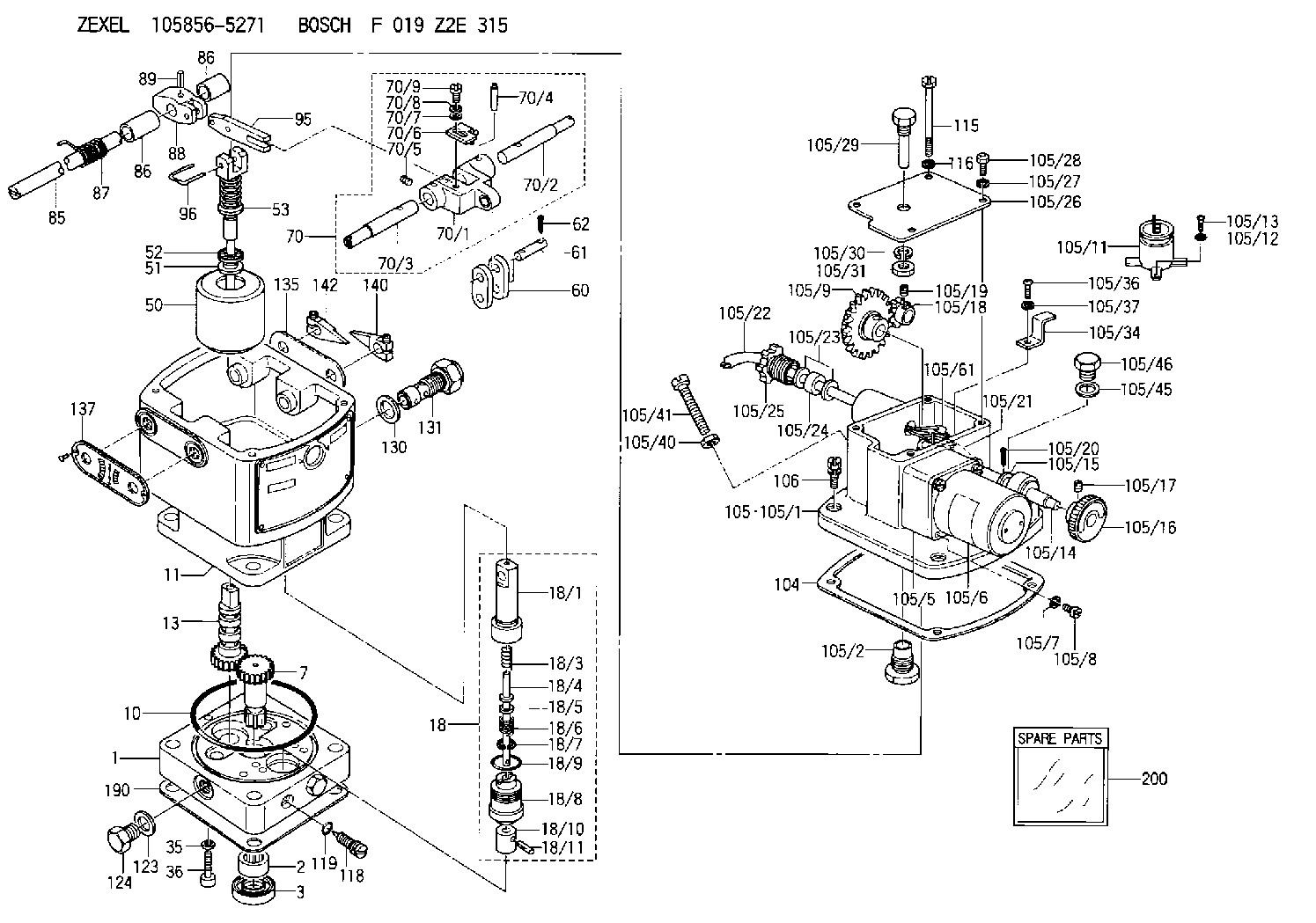
| 1. | [1] | 158502-0420 | BASE |
| 2. | [1] | 029811-8000 | BEARING PLATE |
| 3. | [1] | 158528-0900 | PACKING RING |
| 7. | [1] | 158131-0100 | GEAR SHAFT |
| 10. | [1] | 158028-0000 | O-RING |
| 11. | [1] | 158507-1820 | DIAPHRAGM HOUSING |
| 13. | [1] | 158621-0500 | SLEEVE |
| 18. | [1] | 158699-0321 | COMPENSATOR ASSY |
| 18/1. | [1] | 158610-0901 | POWER PISTON |
| 18/3. | [1] | 158654-0400 | COILED SPRING |
| 18/4. | [1] | 158614-0300 | STOP PIN |
| 18/5. | [1] | 158612-0500 | PLAIN WASHER |
| 18/6. | [1] | 158654-0500 | COILED SPRING |
| 18/7. | [1] | 016110-1220 | LOCKING WASHER |
| 18/8. | [1] | 158612-0001 | BUSHING |
| 18/9. | [2] | 158528-1300 | O-RING |
| 18/10. | [1] | 158615-0300 | PUMP PLUNGER |
| 18/11. | [1] | 025620-1410 | SPRING PIN |
| 35. | [3] | 029330-6070 | GASKET |
| 36. | [3] | 010206-2520 | HEX-SOCKET-HEAD CAP SCREW |
| 50. | [1] | 158600-0720 | FLYWEIGHT ASSEMBLY |
| 51. | [1] | 158106-0100 | PLAIN WASHER |
| 52. | [1] | 029811-0000 | BEARING PLATE |
| 53. | [1] | 158620-1120 | PILOT VALVE |
| 60. | [2] | 158220-0000 | GUIDE LEVER |
| 61. | [2] | 158736-0200 | BEARING PIN |
| 62. | [4] | 025520-1510 | SPLIT PIN |
| 70. | [1] | 158730-0220 | TERMINAL ARM |
| 70/1. | [1] | 158230-0020 | TERMINAL ARM |
| 70/2. | [1] | 158315-0200 | TERMINAL SHAFT |
| 70/3. | [1] | 158315-0200 | TERMINAL SHAFT |
| 70/4. | [2] | 158736-0100 | TAPER PIN |
| 70/5. | [2] | 011006-0620 | SET OF NUTS |
| 70/6. | [1] | 158214-0020 | SPEED DROOP ADJUSTER |
| 70/7. | [1] | 014020-5120 | PLAIN WASHER |
| 70/8. | [1] | 029320-5030 | TAB WASHER |
| 70/9. | [1] | 010535-1220 | FLAT-HEAD SCREW |
| 85. | [1] | 158814-0900 | SPEED CONTROL SHAFT |
| 86. | [2] | 158823-0300 | BUSHING |
| 86. | [2] | 158823-0300 | BUSHING |
| 87. | [1] | 158322-0200 | COILED SPRING |
| 88. | [1] | 158710-0400 | STRAP |
| 89. | [1] | 029404-5010 | BEARING PIN |
| 95. | [1] | 158211-0100 | STRAP |
| 96. | [2] | 158653-0100 | WIRE |
| 104. | [1] | 158017-0900 | GASKET |
| 105. | [1] | 158964-4620 | GOVERNOR MOTOR ASSY |
| 105/1. | [1] | 158962-5110 | CASE |
| 105/2. | [1] | 158903-1920 | SCREW |
| 105/5. | [1] | 158908-2800 | GEAR HEAD |
| 105/6. | [1] | 158908-4200 | MOTOR |
| 105/7. | [4] | 014020-4140 | PLAIN WASHER D8&4.5T0.5 |
| 105/8. | [4] | 158901-8100 | FLAT-HEAD SCREW |
| 105/9. | [1] | 158402-3020 | FRICTION COUPLING |
| 105/11. | [1] | 158908-3900 | CONDENSER |
| 105/12. | [2] | 014110-3440 | LOCKING WASHER |
| 105/13. | [2] | 012153-0840 | FLAT-HEAD SCREW M3P0.5L8 |
| 105/14. | [1] | 158404-1000 | LEVER SHAFT |
| 105/15. | [2] | 014020-8140 | PLAIN WASHER D16&8.5T1.2 |
| 105/16. | [1] | 158904-1920 | ROUND NUT |
| 105/17. | [1] | 158916-0000 | SET OF NUTS |
| 105/18. | [1] | 158404-1100 | TOOTHED GEAR |
| 105/19. | [2] | 011005-0820 | SET OF NUTS |
| 105/20. | [2] | 015320-1540 | SPLIT PIN |
| 105/21. | [1] | 158401-6400 | HOSE |
| 105/22. | [1] | 158401-5000 | WIRE |
| 105/23. | [2] | 158401-7300 | GASKET |
| 105/24. | [1] | 158401-7500 | GASKET |
| 105/25. | [1] | 158401-7400 | GROUND |
| 105/26. | [1] | 158962-6100 | COVER |
| 105/27. | [3] | 014110-5440 | LOCKING WASHER |
| 105/28. | [3] | 012155-1240 | FLAT-HEAD SCREW M5P0.8L12 |
| 105/29. | [1] | 158905-0000 | FILLER PIECE |
| 105/30. | [1] | 014110-8440 | LOCKING WASHER |
| 105/31. | [1] | 013020-8140 | UNION NUT M8P1.25H6.5 |
| 105/34. | [1] | 158906-1800 | CLAMP |
| 105/36. | [1] | 012154-1040 | FLAT-HEAD SCREW M4P0.7L10 |
| 105/37. | [1] | 014110-4440 | LOCKING WASHER |
| 105/40. | [1] | 013020-6040 | UNION NUT M6P1H5 |
| 105/41. | [1] | 158067-0100 | SET OF NUTS |
| 105/45. | [1] | 026512-1640 | GASKET D15.9&12.2T1 |
| 105/46. | [1] | 029111-2070 | CAPSULE M12P1.5L10 |
| 105/61. | [1] | 158950-0100 | TERMINAL |
| 105/120. | [1] | 158908-5100 | CABLE TIE |
| 106. | [3] | 029010-6350 | BLEEDER SCREW M6P1.0L22 |
| 115. | [1] | 029050-6310 | BLEEDER SCREW |
| 116. | [1] | 014110-6440 | LOCKING WASHER |
| 118. | [1] | 158027-0100 | NEEDLE VALVE |
| 119. | [1] | 016500-0710 | O-RING |
| 123. | [2] | 026512-1640 | GASKET D15.9&12.2T1 |
| 124. | [2] | 029111-2070 | CAPSULE M12P1.5L10 |
| 130. | [1] | 029331-8040 | GASKET |
| 131. | [1] | 158660-0020 | CONTROL VALVE |
| 135. | [1] | 158515-0700 | INDICATOR PLATE |
| 137. | [1] | 158515-0800 | INDICATOR PLATE |
| 140. | [1] | 158820-0620 | POINTER |
| 142. | [1] | 158820-0620 | POINTER |
| 190. | [1] | 158017-1000 | GASKET |
| 200. | [1] | 158599-6720 | SPARE PART |
Include in #2:
105856-5271
as INJECTION-PUMP ASSEMBLY
Cross reference number
Zexel num
Bosch num
Firm num
Name
Information:
Remove Rocker Shaft Assemblies And Push Rods
START BY:a. remove valve covers 1. Remove four bolts (1) from the turbocharger tube adapter to the aftercooler housing. Loosen the turbocharger compressor housing clamp, and rotate turbocharger tube (2) out of the way of the cylinder head assembly. 2. Remove bolts (3) that hold the valve cover bases to the cylinder head assembly. Remove valve cover bases (4).
To prevent damage to the fuel injection nozzle, hold adapter assembly (5) in position at the top of injection nozzle (6) when fuel line nut (7) is loosened or tightened.
3. Use tool (A) and a 5P328 crowfoot wrench (7/8") to loosen the fuel injection line nut at the nozzle end. 4. Use tool (B) to loosen the nut at the fuel injection line adapter end. Remove inner fuel injection lines (8). Install caps and plugs on all fuel injection line openings to keep dirt out of the fuel system. 5. Remove bolts (9) that hold the rocker shaft assemblies to the cylinder head assembly.6. Remove rocker shaft assemblies (10). 7. Put identification marks on the push rods as to their location in the engine. Remove push rods (11). 8. Put identification marks on the bridges as to their location in the engine. Remove bridges (12) from the dowels on the cylinder head assembly.Install Rocker Shaft Assemblies And Push Rods
1. Put clean engine oil on the bridges and dowels. Install the original bridges in their respective locations. New bridges can be mixed.2. Install bridges (1) on the bridge dowels. While firmly pressing 0.5 to 4.5 kg (1 to 10 lb.) straight down on the top contact surface of the bridge, turn the adjusting screw clockwise until contact is made with the valve stem. Turn the screw an additional 20° to 30° (1/3 to 1/2 of 1 hex on nut). This will straighten the dowel in the guide and compensate for the slack in the threads. Hold the adjusting screw in this position, and tighten the locknut to a torque of 30 4 N m (22 3 lb.ft.). Install original push rods in their respective locations in the engine. New push rods can be mixed.3. Install push rods (2). 4. Put rocker shaft assemblies (3) in position on the cylinder head assembly.5. Put 5P3931 Anti-Seize Compound on the threads of the bolts that hold the rocker shaft assemblies in place. Tighten the bolts first to a torque of 270 25 N m (200 18 lb.ft.). Start with the bolt in the center of the rocker shaft assembly. Tighten the bolts again to a torque of 450 20 N m (330 15 lb.ft.). Tighten the bolts again by hand to a torque of 450 20 N m (330 15 lb.ft.).
Do not cause damage to the O-ring seals on the inner fuel lines.
6. Install inner fuel injection lines (4). Tighten the fuel injection line adapter nuts (5) to a torque of 40 7 N m (30 5 lb.ft.)