Information hydraulic governor
BOSCH
F 019 Z2E 313
f019z2e313
ZEXEL
105856-5261
1058565261
YANMAR
41660552540
41660552540

Rating:
Components :
| 0. | INJECTION-PUMP ASSEMBLY | 105856-5261 |
| 1. | _ | |
| 2. | FUEL INJECTION PUMP | |
| 3. | NUMBER PLATE | |
| 4. | _ | |
| 5. | CAPSULE | |
| 6. | ADJUSTING DEVICE | |
| 7. | NOZZLE AND HOLDER ASSY | |
| 8. | Nozzle and Holder | |
| 9. | Open Pre:MPa(Kqf/cm2) | |
| 10. | NOZZLE-HOLDER | |
| 11. | NOZZLE |
Scheme ###:
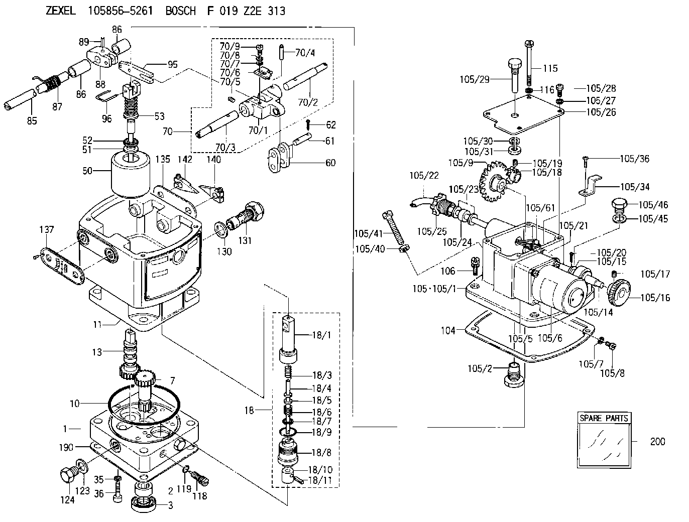
| 1. | [1] | 158502-0420 | BASE |
| 2. | [1] | 029811-8000 | BEARING PLATE |
| 3. | [1] | 158528-0900 | PACKING RING |
| 7. | [1] | 158131-0100 | GEAR SHAFT |
| 10. | [1] | 158028-0000 | O-RING |
| 11. | [1] | 158507-1820 | DIAPHRAGM HOUSING |
| 13. | [1] | 158621-0500 | SLEEVE |
| 18. | [1] | 158699-0321 | COMPENSATOR ASSY |
| 18/1. | [1] | 158610-0901 | POWER PISTON |
| 18/3. | [1] | 158654-0400 | COILED SPRING |
| 18/4. | [1] | 158614-0300 | STOP PIN |
| 18/5. | [1] | 158612-0500 | PLAIN WASHER |
| 18/6. | [1] | 158654-0500 | COILED SPRING |
| 18/7. | [1] | 016110-1220 | LOCKING WASHER |
| 18/8. | [1] | 158612-0001 | BUSHING |
| 18/9. | [2] | 158528-1300 | O-RING |
| 18/10. | [1] | 158615-0300 | PUMP PLUNGER |
| 18/11. | [1] | 025620-1410 | SPRING PIN |
| 35. | [3] | 029330-6070 | GASKET |
| 36. | [3] | 010206-2520 | HEX-SOCKET-HEAD CAP SCREW |
| 50. | [1] | 158600-0720 | FLYWEIGHT ASSEMBLY |
| 51. | [1] | 158106-0100 | PLAIN WASHER |
| 52. | [1] | 029811-0000 | BEARING PLATE |
| 53. | [1] | 158620-1120 | PILOT VALVE |
| 60. | [2] | 158220-0000 | GUIDE LEVER |
| 61. | [2] | 158736-0200 | BEARING PIN |
| 62. | [4] | 025520-1510 | SPLIT PIN |
| 70. | [1] | 158730-0220 | TERMINAL ARM |
| 70/1. | [1] | 158230-0020 | TERMINAL ARM |
| 70/2. | [1] | 158315-0200 | TERMINAL SHAFT |
| 70/3. | [1] | 158315-0200 | TERMINAL SHAFT |
| 70/4. | [2] | 158736-0100 | TAPER PIN |
| 70/5. | [2] | 011006-0620 | SET OF NUTS |
| 70/6. | [1] | 158214-0020 | SPEED DROOP ADJUSTER |
| 70/7. | [1] | 014020-5120 | PLAIN WASHER |
| 70/8. | [1] | 029320-5030 | TAB WASHER |
| 70/9. | [1] | 010535-1220 | FLAT-HEAD SCREW |
| 85. | [1] | 158814-0900 | SPEED CONTROL SHAFT |
| 86. | [2] | 158823-0300 | BUSHING |
| 86. | [2] | 158823-0300 | BUSHING |
| 87. | [1] | 158322-0200 | COILED SPRING |
| 88. | [1] | 158710-0400 | STRAP |
| 89. | [1] | 029404-5010 | BEARING PIN |
| 95. | [1] | 158211-0100 | STRAP |
| 96. | [2] | 158653-0100 | WIRE |
| 104. | [1] | 158017-0900 | GASKET |
| 105. | [1] | 158964-4520 | GOVERNOR MOTOR ASSY |
| 105/1. | [1] | 158962-5110 | CASE |
| 105/2. | [1] | 158903-1920 | SCREW |
| 105/5. | [1] | 158908-2900 | GEAR HEAD |
| 105/6. | [1] | 158901-7200 | MOTOR |
| 105/7. | [4] | 014020-4140 | PLAIN WASHER D8&4.5T0.5 |
| 105/8. | [4] | 158901-8100 | FLAT-HEAD SCREW |
| 105/9. | [1] | 158402-3020 | FRICTION COUPLING |
| 105/14. | [1] | 158404-1000 | LEVER SHAFT |
| 105/15. | [2] | 014020-8140 | PLAIN WASHER D16&8.5T1.2 |
| 105/16. | [1] | 158904-1120 | ROUND NUT |
| 105/17. | [1] | 158916-0000 | SET OF NUTS |
| 105/18. | [1] | 158404-1100 | TOOTHED GEAR |
| 105/19. | [2] | 011005-0820 | SET OF NUTS |
| 105/20. | [2] | 015320-1540 | SPLIT PIN |
| 105/21. | [1] | 158401-6400 | HOSE |
| 105/22. | [1] | 158401-5000 | WIRE |
| 105/23. | [2] | 158401-7300 | GASKET |
| 105/24. | [1] | 158401-7500 | GASKET |
| 105/25. | [1] | 158401-7400 | GROUND |
| 105/26. | [1] | 158962-6100 | COVER |
| 105/27. | [3] | 014110-5440 | LOCKING WASHER |
| 105/28. | [3] | 012155-1240 | FLAT-HEAD SCREW M5P0.8L12 |
| 105/29. | [1] | 158905-0000 | FILLER PIECE |
| 105/30. | [1] | 014110-8440 | LOCKING WASHER |
| 105/31. | [1] | 013020-8140 | UNION NUT M8P1.25H6.5 |
| 105/34. | [1] | 158906-1400 | CLAMP |
| 105/36. | [1] | 012154-0840 | FLAT-HEAD SCREW M4P0.7L8 |
| 105/37. | [1] | 014110-4440 | LOCKING WASHER |
| 105/40. | [1] | 013020-6040 | UNION NUT M6P1H5 |
| 105/41. | [1] | 158067-0100 | SET OF NUTS |
| 105/45. | [1] | 026512-1640 | GASKET D15.9&12.2T1 |
| 105/46. | [1] | 029111-2070 | CAPSULE M12P1.5L10 |
| 105/61. | [2] | 158950-0100 | TERMINAL |
| 106. | [3] | 029010-6350 | BLEEDER SCREW M6P1.0L22 |
| 115. | [1] | 029050-6310 | BLEEDER SCREW |
| 116. | [1] | 014110-6440 | LOCKING WASHER |
| 118. | [1] | 158027-0100 | NEEDLE VALVE |
| 119. | [1] | 016500-0710 | O-RING |
| 123. | [2] | 026512-1640 | GASKET D15.9&12.2T1 |
| 124. | [2] | 029111-2070 | CAPSULE M12P1.5L10 |
| 130. | [1] | 029331-8040 | GASKET |
| 131. | [1] | 158660-0020 | CONTROL VALVE |
| 135. | [1] | 158515-0700 | INDICATOR PLATE |
| 137. | [1] | 158515-0800 | INDICATOR PLATE |
| 140. | [1] | 158820-0620 | POINTER |
| 142. | [1] | 158820-0620 | POINTER |
| 190. | [1] | 158017-1000 | GASKET |
| 200. | [1] | 158599-7020 | SPARE PART |
Include in #2:
105856-5261
as INJECTION-PUMP ASSEMBLY
Cross reference number
Zexel num
Bosch num
Firm num
Name
Information:
1. Install the turbocharger on tool (A) as shown.2. Put alignment marks on three housings of the turbocharger for correct alignment during assembly. Loosen clamp (2), and remove the clamp and housing (1) from housing assembly (3). 3. Loosen clamp (4), and remove housing assembly (3) from housing (5). 4. Put the cartridge group in position in tool (B) as shown.
When the nut is loosened, do not put a side force on the shaft. This can result in a bent shaft.
5. Use a 5S9566 Sliding T-Wrench and a universal socket (6) to remove the nut that holds the compressor wheel to the wheel assembly.6. Remove compressor wheel (7) and the shims from wheel assembly (8).7. Remove housing assembly (3) from wheel assembly (8). 8. Remove ring (9) and backplate (10) from wheel assembly (8). 9. Use tool (C), and remove snap ring (11) from housing assembly (3). 10. Remove insert (12) and sleeve (13) from housing assembly (3). 11. Remove ring (14) from sleeve (13). 12. Remove two screws (15) and deflector (16) from housing assembly (3). 13. Remove ring (18) and bearing assembly (17) from the housing assembly. 14. Remove sleeve (19) and ring (20) from the housing assembly. 15. Remove O-ring seal (23) from the housing assembly.16. Use tool (D), and remove snap ring (22) from the housing assembly.17. Remove bearing (21). Remove the snap ring behind the bearing with tool (D). 18. Use tool (D), and remove snap ring (25) from the housing assembly.19. Remove bearing (24). Remove the snap ring behind the bearing with tool (D).20. Check all the parts of the turbocharger for damage. If the parts are damaged, use new parts for replacement. See Special Instruction, Form No. SMHS6854 for Turbocharger Reconditioning. Also see Guidelines For Reusable Parts, Form No. SEBF8018.Assemble Turbocharger (S4A)
1. Make sure that all of the oil passages in the turbocharger cartridge housing are clean and free of dirt and foreign material. Do not put oil on any parts of the turbocharger until after the compressor wheel has been installed. After the turbocharger has been assembled, pour clean engine oil into the oil inlet of the turbocharger.
Make sure that the snap rings that hold bearings (2) and (5) in position in housing assembly (3) are installed with the round edge of the outside diameter toward the bearing.
2. Install the snap ring behind bearing (2) with tool (A).3. Install bearing (2) in housing assembly (3).4. Use tool (A), and install snap ring (1) in the housing assembly. 5. Install the snap ring behind bearing (5) with tool (A).6. Install bearing (5) in the housing assembly.7. Use tool (A), and install snap ring (4) in the housing assembly. 8. Put wheel assembly (8) in position on tool (B) as shown.9. Put backplate (7) in position on the wheel assembly. Put 6V2055 High Vacuum Grease