Information hydraulic governor
BOSCH
F 019 Z1F 191
f019z1f191
ZEXEL
105856-5241
1058565241

Rating:
Components :
| 0. | INJECTION-PUMP ASSEMBLY | 105856-5241 |
| 1. | _ | |
| 2. | FUEL INJECTION PUMP | |
| 3. | NUMBER PLATE | |
| 4. | _ | |
| 5. | CAPSULE | |
| 6. | ADJUSTING DEVICE | |
| 7. | NOZZLE AND HOLDER ASSY | |
| 8. | Nozzle and Holder | |
| 9. | Open Pre:MPa(Kqf/cm2) | |
| 10. | NOZZLE-HOLDER | |
| 11. | NOZZLE |
Scheme ###:
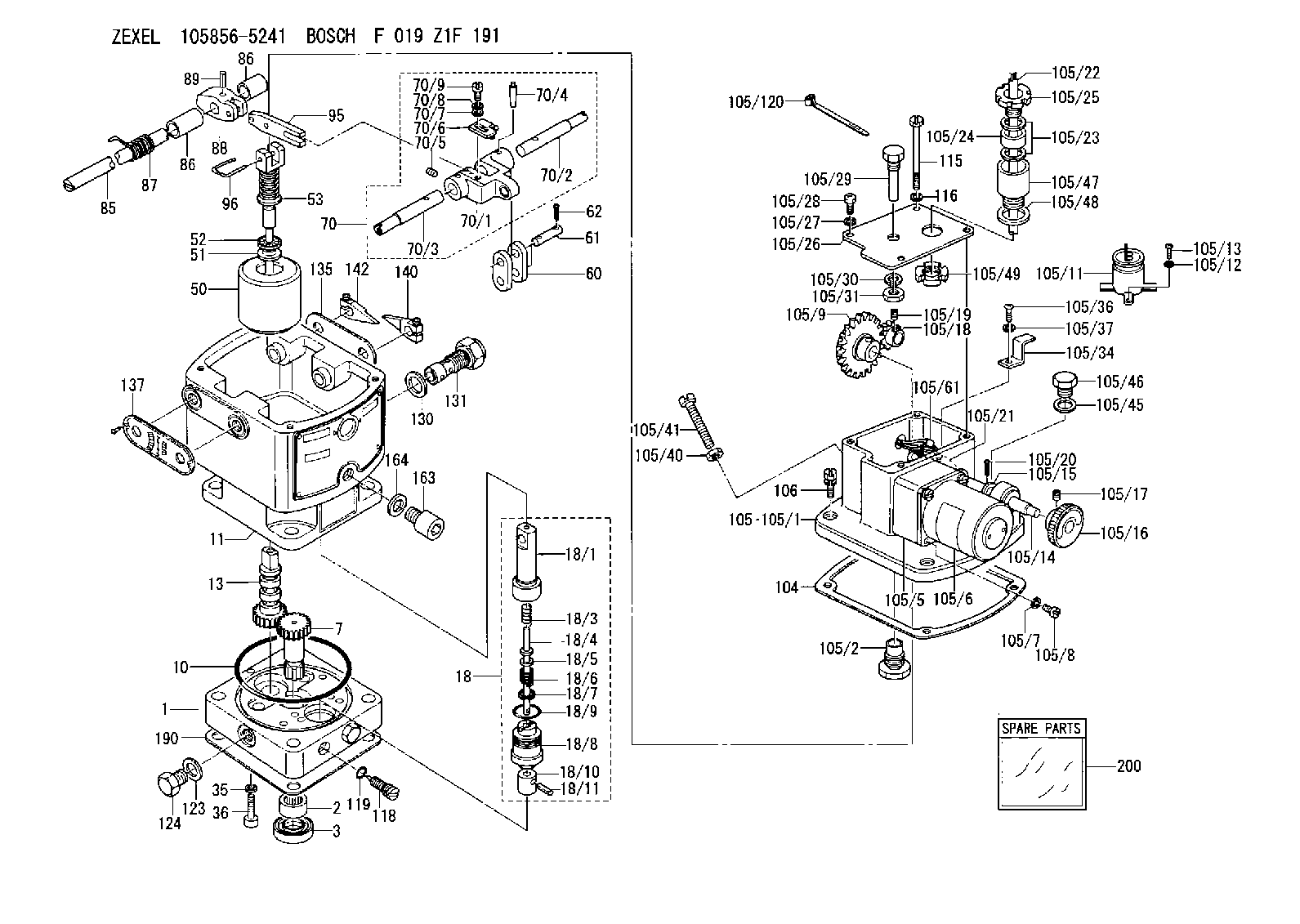
| 1. | [1] | 158502-0420 | BASE |
| 2. | [1] | 029811-8000 | BEARING PLATE |
| 3. | [1] | 158528-0900 | PACKING RING |
| 7. | [1] | 158131-0100 | GEAR SHAFT |
| 10. | [1] | 158028-0000 | O-RING |
| 11. | [1] | 158507-1120 | DIAPHRAGM HOUSING |
| 13. | [1] | 158621-0500 | SLEEVE |
| 18. | [1] | 158699-0521 | COMPENSATOR ASSY |
| 18/1. | [1] | 158610-0901 | POWER PISTON |
| 18/3. | [1] | 158654-1000 | COILED SPRING |
| 18/4. | [1] | 158614-0300 | STOP PIN |
| 18/5. | [1] | 158612-0500 | PLAIN WASHER |
| 18/6. | [1] | 158654-1100 | COILED SPRING |
| 18/7. | [1] | 016110-1220 | LOCKING WASHER |
| 18/8. | [1] | 158612-0001 | BUSHING |
| 18/9. | [2] | 158528-1300 | O-RING |
| 18/10. | [1] | 158615-0400 | PUMP PLUNGER |
| 18/11. | [1] | 025620-1410 | SPRING PIN |
| 35. | [3] | 029330-6070 | GASKET |
| 36. | [3] | 010206-2520 | HEX-SOCKET-HEAD CAP SCREW |
| 50. | [1] | 158600-1020 | FLYWEIGHT ASSEMBLY |
| 51. | [1] | 158106-0100 | PLAIN WASHER |
| 52. | [1] | 029811-0000 | BEARING PLATE |
| 53. | [1] | 158620-1220 | PILOT VALVE |
| 60. | [2] | 158220-0000 | GUIDE LEVER |
| 61. | [2] | 158736-0200 | BEARING PIN |
| 62. | [4] | 025520-1510 | SPLIT PIN |
| 70. | [1] | 158730-0220 | TERMINAL ARM |
| 70/1. | [1] | 158230-0020 | TERMINAL ARM |
| 70/2. | [1] | 158315-0200 | TERMINAL SHAFT |
| 70/3. | [1] | 158315-0200 | TERMINAL SHAFT |
| 70/4. | [2] | 158736-0100 | TAPER PIN |
| 70/5. | [2] | 011006-0620 | SET OF NUTS |
| 70/6. | [1] | 158214-0020 | SPEED DROOP ADJUSTER |
| 70/7. | [1] | 014020-5120 | PLAIN WASHER |
| 70/8. | [1] | 029320-5030 | TAB WASHER |
| 70/9. | [1] | 010535-1220 | FLAT-HEAD SCREW |
| 85. | [1] | 158814-1000 | SPEED CONTROL SHAFT |
| 86. | [2] | 158823-0300 | BUSHING |
| 86. | [2] | 158823-0300 | BUSHING |
| 87. | [1] | 158322-0200 | COILED SPRING |
| 88. | [1] | 158710-0400 | STRAP |
| 89. | [1] | 029404-5010 | BEARING PIN |
| 95. | [1] | 158211-0100 | STRAP |
| 96. | [2] | 158653-0100 | WIRE |
| 104. | [1] | 158017-0900 | GASKET |
| 105. | [1] | 158963-8521 | GOVERNOR MOTOR ASSY |
| 105/1. | [1] | 158964-9210 | CASE |
| 105/2. | [1] | 158903-1920 | SCREW |
| 105/5. | [1] | 158908-6600 | GEAR HEAD |
| 105/6. | [1] | 158908-5020 | MOTOR |
| 105/7. | [4] | 014020-4140 | PLAIN WASHER D8&4.5T0.5 |
| 105/8. | [4] | 158901-8100 | FLAT-HEAD SCREW |
| 105/9. | [1] | 158402-3020 | FRICTION COUPLING |
| 105/11. | [1] | 158908-3900 | CONDENSER |
| 105/12. | [2] | 014110-3440 | LOCKING WASHER |
| 105/13. | [2] | 012153-0840 | FLAT-HEAD SCREW M3P0.5L8 |
| 105/14. | [1] | 158404-1000 | LEVER SHAFT |
| 105/15. | [2] | 014020-8140 | PLAIN WASHER D16&8.5T1.2 |
| 105/16. | [1] | 158904-1920 | ROUND NUT |
| 105/17. | [1] | 158916-0000 | SET OF NUTS |
| 105/18. | [1] | 158404-1100 | TOOTHED GEAR |
| 105/19. | [2] | 011005-0820 | SET OF NUTS |
| 105/20. | [2] | 015320-1540 | SPLIT PIN |
| 105/21. | [1] | 158401-6400 | HOSE |
| 105/22. | [1] | 158401-5000 | WIRE |
| 105/23. | [2] | 158401-7300 | GASKET |
| 105/24. | [1] | 158401-7500 | GASKET |
| 105/25. | [1] | 158401-7400 | GROUND |
| 105/26. | [1] | 158962-7200 | COVER |
| 105/27. | [3] | 014110-5440 | LOCKING WASHER |
| 105/28. | [3] | 012155-1240 | FLAT-HEAD SCREW M5P0.8L12 |
| 105/29. | [1] | 158905-0000 | FILLER PIECE |
| 105/30. | [1] | 014110-8440 | LOCKING WASHER |
| 105/31. | [1] | 013020-8140 | UNION NUT M8P1.25H6.5 |
| 105/34. | [1] | 158906-1800 | CLAMP |
| 105/36. | [1] | 012154-1040 | FLAT-HEAD SCREW M4P0.7L10 |
| 105/37. | [1] | 014110-4440 | LOCKING WASHER |
| 105/40. | [1] | 013020-6040 | UNION NUT M6P1H5 |
| 105/41. | [1] | 158067-0100 | SET OF NUTS |
| 105/45. | [1] | 026512-1640 | GASKET D15.9&12.2T1 |
| 105/46. | [1] | 029111-2070 | CAPSULE M12P1.5L10 |
| 105/47. | [1] | 158901-6200 | ADAPTOR |
| 105/48. | [1] | 158901-6300 | GASKET |
| 105/49. | [1] | 158901-6400 | UNION NUT |
| 105/61. | [1] | 158950-0100 | TERMINAL |
| 105/120. | [1] | 158908-5100 | CABLE TIE |
| 106. | [3] | 029010-6350 | BLEEDER SCREW M6P1.0L22 |
| 115. | [1] | 029050-6310 | BLEEDER SCREW |
| 116. | [1] | 014110-6440 | LOCKING WASHER |
| 118. | [1] | 158527-0200 | NEEDLE VALVE |
| 119. | [1] | 016500-0710 | O-RING |
| 123. | [2] | 026512-1640 | GASKET D15.9&12.2T1 |
| 124. | [2] | 029111-2070 | CAPSULE M12P1.5L10 |
| 130. | [1] | 029331-8040 | GASKET |
| 131. | [1] | 158660-0320 | CONTROL VALVE |
| 135. | [1] | 158515-0700 | INDICATOR PLATE |
| 137. | [1] | 158515-0800 | INDICATOR PLATE |
| 140. | [1] | 158820-0620 | POINTER |
| 142. | [1] | 158820-0620 | POINTER |
| 163. | [1] | 010210-1420 | HEX-SOCKET-HEAD CAP SCREW |
| 164. | [1] | 026510-1340 | GASKET D13.4&10.2T1 |
| 190. | [1] | 158017-1000 | GASKET |
| 200. | [1] | 158599-6720 | SPARE PART |
Include in #2:
105856-5241
as INJECTION-PUMP ASSEMBLY
Cross reference number
Zexel num
Bosch num
Firm num
Name
HYDRAULIC GOVERNOR
* K 35AA HYDRAULIC GOVERNOR Hydraulic RHD6 Others
* K 35AA HYDRAULIC GOVERNOR Hydraulic RHD6 Others
Information:
START BY:a. disassemble governorb. remove fuel injection pumps 1. Remove rack (1) from the fuel pump housing. 2. Remove six lifters (2) from the fuel pump housing. Put identification marks on the lifters for installation purposes. 3. Remove camshaft (3) from the fuel pump housing. It may be necessary to use a soft hammer to push the camshaft out of the governor end of the fuel pump housing. 4. Remove races (4) and bearing (5) from the camshaft. Remove ring (6) if necessary. 5. Remove rack bearing (7) from both ends of the housing and dowel (8) if necessary. 6. Use tooling (A), and remove three camshaft bearings (9). 7. Remove the bolts, cover (10) and the gasket. 8. Remove pins (12), the seal and dowels (11) if necessary. Pins (12) must be pushed from the inside out.Assemble Fuel Injection Pump Housing
1. Clean and inspect all parts. Make a replacement of all parts that are worn or damaged. 2. Lubricate the seal with clean engine oil, and install pin (1). Pin (1) must protrude into the pump bore 2.15 .05 mm (.085 .002 in.).3. Install dowel (2) so that it protrudes into the pump bore 1.93 0.05 mm (.076 .002 in.). 4. Install the gasket, cover (3) and the bolts. 5. Install the rack bearing with tooling (A). Install the bearing until the driver comes in contact with the plate. The bearing should be installed to a depth of 83.0 0.5 mm (3.27 .02 in.) from the fuel pump mounting face. 6. Measure rack bearing (4). Dimension (X) must be 11.178 0.05 mm (.4400 .002 in.). Diameter (W) must be 12.767 0.058 mm (.5026 .0022 in.). 7. Install dowel (5). Dowel (5) must protrude 6.0 0.5 mm (.24 .02 in.) from the fuel pump housing face.8. Install the rear rack bearing with tooling (B) to a depth of 7.16 0.13 mm (.282 .005 in.) below the fuel pump housing surface. The inside diameter of the rear rack bearing must be 12.746 0.045 mm (.5018 .0017 in.). 9. Use tooling (C), and install three camshaft bearings (6). Oil holes (7) in the camshaft bearings must be positioned 30° 3° above the horizontal centerline toward the engine side of the fuel pump housing. The outer bearings must be installed 1.0 0.5 mm (0.04 0.02 in.) below the surface marked (Z). The inner bearing must be installed 218.0 0.3 mm (8.58 .012 in.) below the front surface (Y). Diameter (XX) must be 68.339 0.038 mm (2.6905 .0015 in.) after assembly. 10. Install ring (8), races (10) and bearing (9) on the camshaft. 11. Lubricate cam bearings (6) and the camshaft bearing journals with clean engine oil.12. Install camshaft (11) into the fuel pump housing.
The notch in the lifter must be in line with the dowel in the lifter bore. The lifter must slide up and down freely in