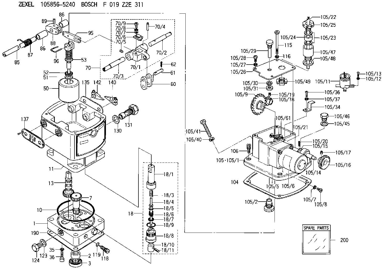
Information hydraulic governor
BOSCH
F 019 Z2E 311
f019z2e311
ZEXEL
105856-5240
1058565240
DAIHATSU
QGDK307400FZ
qgdk307400fz

Rating:
Components :
| 0. | INJECTION-PUMP ASSEMBLY | 105856-5240 |
| 1. | _ | |
| 2. | FUEL INJECTION PUMP | |
| 3. | NUMBER PLATE | |
| 4. | _ | |
| 5. | CAPSULE | |
| 6. | ADJUSTING DEVICE | |
| 7. | NOZZLE AND HOLDER ASSY | |
| 8. | Nozzle and Holder | |
| 9. | Open Pre:MPa(Kqf/cm2) | |
| 10. | NOZZLE-HOLDER | |
| 11. | NOZZLE |
Scheme ###:
| 1. | [1] | 158502-0420 | BASE |
| 2. | [1] | 029811-8000 | BEARING PLATE |
| 3. | [1] | 158528-0900 | PACKING RING |
| 7. | [1] | 158131-0100 | GEAR SHAFT |
| 10. | [1] | 158028-0000 | O-RING |
| 11. | [1] | 158507-1820 | DIAPHRAGM HOUSING |
| 13. | [1] | 158621-0500 | SLEEVE |
| 18. | [1] | 158699-0521 | COMPENSATOR ASSY |
| 18/1. | [1] | 158610-0901 | POWER PISTON |
| 18/3. | [1] | 158654-1000 | COILED SPRING |
| 18/4. | [1] | 158614-0300 | STOP PIN |
| 18/5. | [1] | 158612-0500 | PLAIN WASHER |
| 18/6. | [1] | 158654-1100 | COILED SPRING |
| 18/7. | [1] | 016110-1220 | LOCKING WASHER |
| 18/8. | [1] | 158612-0001 | BUSHING |
| 18/9. | [2] | 158528-1300 | O-RING |
| 18/10. | [1] | 158615-0400 | PUMP PLUNGER |
| 18/11. | [1] | 025620-1410 | SPRING PIN |
| 35. | [3] | 029330-6070 | GASKET |
| 36. | [3] | 010206-2520 | HEX-SOCKET-HEAD CAP SCREW |
| 50. | [1] | 158600-1020 | FLYWEIGHT ASSEMBLY |
| 51. | [1] | 158106-0100 | PLAIN WASHER |
| 52. | [1] | 029811-0000 | BEARING PLATE |
| 53. | [1] | 158620-1220 | PILOT VALVE |
| 60. | [2] | 158220-0000 | GUIDE LEVER |
| 61. | [2] | 158736-0200 | BEARING PIN |
| 62. | [4] | 025520-1510 | SPLIT PIN |
| 70. | [1] | 158730-0220 | TERMINAL ARM |
| 70/1. | [1] | 158230-0020 | TERMINAL ARM |
| 70/2. | [1] | 158315-0200 | TERMINAL SHAFT |
| 70/3. | [1] | 158315-0200 | TERMINAL SHAFT |
| 70/4. | [2] | 158736-0100 | TAPER PIN |
| 70/5. | [2] | 011006-0620 | SET OF NUTS |
| 70/6. | [1] | 158214-0020 | SPEED DROOP ADJUSTER |
| 70/7. | [1] | 014020-5120 | PLAIN WASHER |
| 70/8. | [1] | 029320-5030 | TAB WASHER |
| 70/9. | [1] | 010535-1220 | FLAT-HEAD SCREW |
| 85. | [1] | 158814-1000 | SPEED CONTROL SHAFT |
| 86. | [2] | 158823-0300 | BUSHING |
| 86. | [2] | 158823-0300 | BUSHING |
| 87. | [1] | 158322-0200 | COILED SPRING |
| 88. | [1] | 158710-0400 | STRAP |
| 89. | [1] | 029404-5010 | BEARING PIN |
| 95. | [1] | 158211-0100 | STRAP |
| 96. | [2] | 158653-0100 | WIRE |
| 104. | [1] | 158017-0900 | GASKET |
| 105. | [1] | 158963-8520 | GOVERNOR MOTOR ASSY |
| 105/1. | [1] | 158962-7310 | CASE |
| 105/2. | [1] | 158903-1920 | SCREW |
| 105/5. | [1] | 158908-3700 | GEAR HEAD |
| 105/6. | [1] | 158908-4200 | MOTOR |
| 105/7. | [4] | 014020-4140 | PLAIN WASHER D8&4.5T0.5 |
| 105/8. | [4] | 158901-8100 | FLAT-HEAD SCREW |
| 105/9. | [1] | 158402-3020 | FRICTION COUPLING |
| 105/11. | [1] | 158908-3900 | CONDENSER |
| 105/12. | [2] | 014110-3440 | LOCKING WASHER |
| 105/13. | [2] | 012153-0840 | FLAT-HEAD SCREW M3P0.5L8 |
| 105/14. | [1] | 158404-1000 | LEVER SHAFT |
| 105/15. | [2] | 014020-8140 | PLAIN WASHER D16&8.5T1.2 |
| 105/16. | [1] | 158904-1920 | ROUND NUT |
| 105/17. | [1] | 158916-0000 | SET OF NUTS |
| 105/18. | [1] | 158404-1100 | TOOTHED GEAR |
| 105/19. | [2] | 011005-0820 | SET OF NUTS |
| 105/20. | [2] | 015320-1540 | SPLIT PIN |
| 105/21. | [1] | 158401-6400 | HOSE |
| 105/22. | [1] | 158401-5000 | WIRE |
| 105/23. | [2] | 158401-7300 | GASKET |
| 105/24. | [1] | 158401-7500 | GASKET |
| 105/25. | [1] | 158401-7400 | GROUND |
| 105/26. | [1] | 158962-7200 | COVER |
| 105/27. | [3] | 014110-5440 | LOCKING WASHER |
| 105/28. | [3] | 012155-1240 | FLAT-HEAD SCREW M5P0.8L12 |
| 105/29. | [1] | 158905-0000 | FILLER PIECE |
| 105/30. | [1] | 014110-8440 | LOCKING WASHER |
| 105/31. | [1] | 013020-8140 | UNION NUT M8P1.25H6.5 |
| 105/34. | [1] | 158906-1800 | CLAMP |
| 105/36. | [1] | 012154-1040 | FLAT-HEAD SCREW M4P0.7L10 |
| 105/37. | [1] | 014110-4440 | LOCKING WASHER |
| 105/40. | [1] | 013020-6040 | UNION NUT M6P1H5 |
| 105/41. | [1] | 158067-0100 | SET OF NUTS |
| 105/45. | [1] | 026512-1640 | GASKET D15.9&12.2T1 |
| 105/46. | [1] | 029111-2070 | CAPSULE M12P1.5L10 |
| 105/47. | [1] | 158901-6200 | ADAPTOR |
| 105/48. | [1] | 158901-6300 | GASKET |
| 105/49. | [1] | 158901-6400 | UNION NUT |
| 105/61. | [1] | 158950-0100 | TERMINAL |
| 106. | [3] | 029010-6350 | BLEEDER SCREW M6P1.0L22 |
| 115. | [1] | 029050-6310 | BLEEDER SCREW |
| 116. | [1] | 014110-6440 | LOCKING WASHER |
| 118. | [1] | 158527-0200 | NEEDLE VALVE |
| 119. | [1] | 016500-0710 | O-RING |
| 123. | [2] | 026512-1640 | GASKET D15.9&12.2T1 |
| 124. | [2] | 029111-2070 | CAPSULE M12P1.5L10 |
| 130. | [1] | 029331-8040 | GASKET |
| 131. | [1] | 158660-0320 | CONTROL VALVE |
| 135. | [1] | 158515-0700 | INDICATOR PLATE |
| 137. | [1] | 158515-0800 | INDICATOR PLATE |
| 140. | [1] | 158820-0620 | POINTER |
| 142. | [1] | 158820-0620 | POINTER |
| 190. | [1] | 158017-1000 | GASKET |
| 200. | [1] | 158599-6720 | SPARE PART |
Include in #2:
105856-5240
as INJECTION-PUMP ASSEMBLY
Cross reference number
Zexel num
Bosch num
Firm num
Name
F 019 Z2E 311
QGDK307400FZ DAIHATSU
HYDRAULIC GOVERNOR
* K 35AA Hydraulic RHD6 Others
* K 35AA Hydraulic RHD6 Others
Information:
START BY:a. remove fuel injection linesb. disassemble governor**Only disassemble the governor enough so that tooling (D) of Install Fuel Injection Pump can be installed. 1. Remove the plug, and move the rack until tool (A) can be installed to hold the rack in the center position. The rack must be in the center position to remove the fuel injection pumps.
To prevent possible personal injury carefully follow the steps below.
2. Put tooling (B) except for the 8S4613 Wrench in position on the fuel pump housing as shown. Lower the handle to center the adjusting screw with the fuel line seat. With the handle down in the locked position, the adjusting screw must just be in contact with fuel line seat (1). If force is needed to lower the handle or there is a gap, remove the tooling, and make an adjustment to the screw.3. Loosen bushing (2) 1/4 of a turn.4. Put tooling (B) in position on the pump housing with the handle down in the locked position as shown.5. Remove bushing (2) from the pump housing.6. Carefully and slowly lift the handle to release the spring force. Remove the tooling. 7. Install tool (C) on fuel pump (4) as shown.8. Remove seal (3) and fuel pump (4) from the fuel pump housing. 9. Remove spacers (5) from the pump housing. There must be a pump installed on either side of the pump to be removed to install tooling (B). If there is no pump, take a pump already removed, and remove the spring so there will be no spring force, and install it in the pump housing. See Install Fuel Pump. Spacers (5) are the same thickness for each fuel injection pump so they can be mixed. The fuel injection pump plungers and barrels are sets and cannot be mixed.Install Fuel Injection Pumps
1. Install spacers (2) in the fuel pump housing.2. Move the rack until tool (A) can be installed to hold the rack in the center position. The rack must be in the center position to install the fuel injection pumps.3. Install a fuel pump without its spring so that tool (C) can be installed. See Step 5 for correct fuel pump installation. 4. Install tool (B) on the bonnet of the fuel pump as shown.5. Install the fuel pump in the pump housing with the saw cut (slot) (5) in the gear in alignment with small pin (1) in the lifter assembly and groove (4) in the barrel in alignment with large pin (3) in the pump housing. 6. Install the seal and bushing (6) on the fuel pump.7. Put tooling (C) in position on the fuel pump housing as shown.8. Lower the handle slowly and carefully. If the fuel pump is not installed correctly, the handle will not go all the way down. Do not try to use force on it. Remove and install the tooling and the fuel pump again.9. Make sure the seal is in its correct position, and start to tighten bushing