Information hydraulic governor
BOSCH
F 019 Z2E 309
f019z2e309
ZEXEL
105856-5220
1058565220
MITSUBISHI-HEAV
3756401600
3756401600

Rating:
Components :
| 0. | INJECTION-PUMP ASSEMBLY | 105856-5220 |
| 1. | _ | |
| 2. | FUEL INJECTION PUMP | |
| 3. | NUMBER PLATE | |
| 4. | _ | |
| 5. | CAPSULE | |
| 6. | ADJUSTING DEVICE | |
| 7. | NOZZLE AND HOLDER ASSY | |
| 8. | Nozzle and Holder | |
| 9. | Open Pre:MPa(Kqf/cm2) | |
| 10. | NOZZLE-HOLDER | |
| 11. | NOZZLE |
Scheme ###:
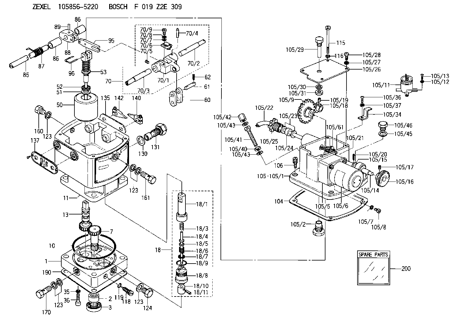
| 1. | [1] | 158502-0620 | BASE |
| 2. | [1] | 029811-8000 | BEARING PLATE |
| 3. | [1] | 158528-0900 | PACKING RING |
| 7. | [1] | 158131-0100 | GEAR SHAFT |
| 10. | [1] | 158028-0000 | O-RING |
| 11. | [1] | 158507-1420 | DIAPHRAGM HOUSING |
| 13. | [1] | 158621-0500 | SLEEVE |
| 18. | [1] | 158699-0321 | COMPENSATOR ASSY |
| 18/1. | [1] | 158610-0901 | POWER PISTON |
| 18/3. | [1] | 158654-0400 | COILED SPRING |
| 18/4. | [1] | 158614-0300 | STOP PIN |
| 18/5. | [1] | 158612-0500 | PLAIN WASHER |
| 18/6. | [1] | 158654-0500 | COILED SPRING |
| 18/7. | [1] | 016110-1220 | LOCKING WASHER |
| 18/8. | [1] | 158612-0001 | BUSHING |
| 18/9. | [2] | 158528-1300 | O-RING |
| 18/10. | [1] | 158615-0300 | PUMP PLUNGER |
| 18/11. | [1] | 025620-1410 | SPRING PIN |
| 35. | [3] | 029330-6070 | GASKET |
| 36. | [3] | 010206-2520 | HEX-SOCKET-HEAD CAP SCREW |
| 50. | [1] | 158600-0720 | FLYWEIGHT ASSEMBLY |
| 51. | [1] | 158106-0100 | PLAIN WASHER |
| 52. | [1] | 029811-0000 | BEARING PLATE |
| 53. | [1] | 158620-1120 | PILOT VALVE |
| 60. | [2] | 158220-0000 | GUIDE LEVER |
| 61. | [2] | 158736-0200 | BEARING PIN |
| 62. | [4] | 025520-1510 | SPLIT PIN |
| 70. | [1] | 158730-0920 | TERMINAL ARM |
| 70/1. | [1] | 158230-0020 | TERMINAL ARM |
| 70/2. | [1] | 158815-0700 | TERMINAL SHAFT |
| 70/3. | [1] | 158815-0600 | TERMINAL SHAFT |
| 70/4. | [2] | 158736-0100 | TAPER PIN |
| 70/5. | [2] | 011006-0620 | SET OF NUTS |
| 70/6. | [1] | 158214-0020 | SPEED DROOP ADJUSTER |
| 70/7. | [1] | 014020-5120 | PLAIN WASHER |
| 70/8. | [1] | 029320-5030 | TAB WASHER |
| 70/9. | [1] | 010535-1220 | FLAT-HEAD SCREW |
| 85. | [1] | 158814-1800 | SPEED CONTROL SHAFT |
| 86. | [2] | 158823-0300 | BUSHING |
| 86. | [2] | 158823-0300 | BUSHING |
| 87. | [1] | 158322-0200 | COILED SPRING |
| 88. | [1] | 158710-0400 | STRAP |
| 89. | [1] | 029404-5010 | BEARING PIN |
| 95. | [1] | 158211-0100 | STRAP |
| 96. | [2] | 158653-0100 | WIRE |
| 104. | [1] | 158017-0900 | GASKET |
| 105. | [1] | 158964-1820 | GOVERNOR MOTOR ASSY |
| 105/1. | [1] | 158563-1010 | CASE |
| 105/2. | [1] | 158903-2220 | SCREW |
| 105/5. | [1] | 158908-3700 | GEAR HEAD |
| 105/6. | [1] | 158908-4200 | MOTOR |
| 105/7. | [4] | 014020-4140 | PLAIN WASHER D8&4.5T0.5 |
| 105/8. | [4] | 158901-8100 | FLAT-HEAD SCREW |
| 105/9. | [1] | 158402-3020 | FRICTION COUPLING |
| 105/11. | [1] | 158908-3900 | CONDENSER |
| 105/12. | [2] | 014110-3440 | LOCKING WASHER |
| 105/13. | [2] | 012153-0840 | FLAT-HEAD SCREW M3P0.5L8 |
| 105/14. | [1] | 158404-1000 | LEVER SHAFT |
| 105/15. | [2] | 014020-8140 | PLAIN WASHER D16&8.5T1.2 |
| 105/16. | [1] | 158904-1920 | ROUND NUT |
| 105/17. | [1] | 158916-0000 | SET OF NUTS |
| 105/18. | [1] | 158404-1100 | TOOTHED GEAR |
| 105/19. | [2] | 011005-0820 | SET OF NUTS |
| 105/20. | [2] | 015320-1540 | SPLIT PIN |
| 105/21. | [1] | 158401-6400 | HOSE |
| 105/22. | [1] | 158401-5000 | WIRE |
| 105/23. | [2] | 158401-7300 | GASKET |
| 105/24. | [1] | 158401-7500 | GASKET |
| 105/25. | [1] | 158401-7400 | GROUND |
| 105/26. | [1] | 158962-6100 | COVER |
| 105/27. | [3] | 014110-5440 | LOCKING WASHER |
| 105/28. | [3] | 012155-1240 | FLAT-HEAD SCREW M5P0.8L12 |
| 105/29. | [1] | 158905-0000 | FILLER PIECE |
| 105/30. | [1] | 014110-8440 | LOCKING WASHER |
| 105/31. | [1] | 013020-8140 | UNION NUT M8P1.25H6.5 |
| 105/34. | [1] | 158906-1800 | CLAMP |
| 105/36. | [1] | 012154-0840 | FLAT-HEAD SCREW M4P0.7L8 |
| 105/37. | [1] | 014110-4440 | LOCKING WASHER |
| 105/40. | [1] | 029240-6020 | UNION NUT |
| 105/41. | [1] | 158067-0400 | SET OF NUTS |
| 105/42. | [1] | 154035-1600 | CAP NUT |
| 105/43. | [2] | 029330-6070 | GASKET |
| 105/43. | [2] | 029330-6070 | GASKET |
| 105/45. | [1] | 026512-1640 | GASKET D15.9&12.2T1 |
| 105/46. | [1] | 029111-2070 | CAPSULE M12P1.5L10 |
| 105/61. | [1] | 158950-0100 | TERMINAL |
| 105/120. | [1] | 158908-5100 | CABLE TIE |
| 106. | [3] | 029010-6350 | BLEEDER SCREW M6P1.0L22 |
| 115. | [1] | 029050-6310 | BLEEDER SCREW |
| 116. | [1] | 014110-6440 | LOCKING WASHER |
| 118. | [1] | 158027-0100 | NEEDLE VALVE |
| 119. | [1] | 016500-0710 | O-RING |
| 123. | [6] | 026512-1640 | GASKET D15.9&12.2T1 |
| 123. | [6] | 026512-1640 | GASKET D15.9&12.2T1 |
| 123. | [6] | 026512-1640 | GASKET D15.9&12.2T1 |
| 123. | [6] | 026512-1640 | GASKET D15.9&12.2T1 |
| 124. | [2] | 029111-2070 | CAPSULE M12P1.5L10 |
| 130. | [1] | 029331-8040 | GASKET |
| 131. | [1] | 158660-0520 | CONTROL VALVE |
| 135. | [1] | 158515-0700 | INDICATOR PLATE |
| 137. | [1] | 158515-0800 | INDICATOR PLATE |
| 140. | [1] | 158820-0620 | POINTER |
| 142. | [1] | 158820-0620 | POINTER |
| 160. | [1] | 029111-2070 | CAPSULE M12P1.5L10 |
| 161. | [1] | 158521-0600 | EYE BOLT |
| 170. | [1] | 158521-0700 | EYE BOLT |
| 190. | [1] | 158017-1000 | GASKET |
| 200. | [1] | 158599-5620 | SPARE PART |
Include in #2:
105856-5220
as INJECTION-PUMP ASSEMBLY
Cross reference number
Zexel num
Bosch num
Firm num
Name
Information:
1. Disconnect fuel line (1) from the fuel transfer pump. Disconnect fuel line (2) from the fuel injection pump housing. Remove line (3) from the fuel ratio control and aftercooler housing. 2. Disconnect fuel injection lines (4) from the fuel injection pump housing.
Do not disconnect the air line from the air compressor governor until the air pressure is zero.
3. Loosen the bleed valves, and release the air pressure in the air tank. 4. Remove air line (5). Remove coolant line (6). 5. The weight of the fuel injection pump housing and governor is 57 kg (125 lb.). Attach a hoist to the fuel injection pump housing, and remove bolts (7). 6. Remove the two nuts and two bolts (8) and bolt (9). Remove fuel injection pump housing and governor (10). 7. Remove O-ring seals (11) from the fuel injection pump housing.Install Fuel Injection Pump Housing And Governor
1. Attach a hoist to the fuel injection pump housing and governor (1). Be sure that the three O-ring seals are in position in the fuel injection pump housing. Install the fuel injection pump housing and governor on the timing gear housing. 2. Connect air line (2) and water line (3) to the air compressor. 3. Connect fuel injection lines (4) to fuel injection pump housing, and tighten the fuel injection line nuts to a torque of 40 7 N m (30 5 lb.ft.) with tool (C). 4. Connect fuel line (5) to fuel injection pump housing, and connect fuel line (6) to the fuel transfer pump. Install line (7) between the fuel ratio control and aftercooler housing. For timing of the fuel injection pump, see Install Automatic Timing Advance.END BY:a. install automatic timing advance