Information hydraulic governor
BOSCH
F 019 Z2E 307
f019z2e307
ZEXEL
105856-5200
1058565200
MITSUBISHI-HEAV
3756401400
3756401400

Rating:
Components :
| 0. | INJECTION-PUMP ASSEMBLY | 105856-5200 |
| 1. | _ | |
| 2. | FUEL INJECTION PUMP | |
| 3. | NUMBER PLATE | |
| 4. | _ | |
| 5. | CAPSULE | |
| 6. | ADJUSTING DEVICE | |
| 7. | NOZZLE AND HOLDER ASSY | |
| 8. | Nozzle and Holder | |
| 9. | Open Pre:MPa(Kqf/cm2) | |
| 10. | NOZZLE-HOLDER | |
| 11. | NOZZLE |
Scheme ###:
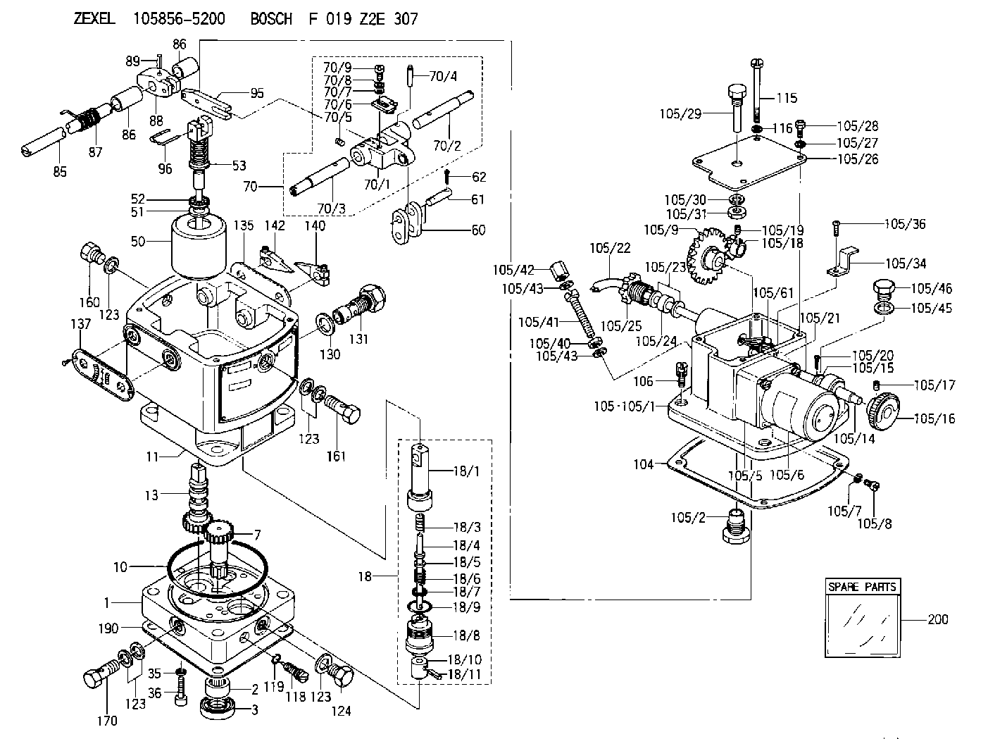
| 1. | [1] | 158502-0620 | BASE |
| 2. | [1] | 029811-8000 | BEARING PLATE |
| 3. | [1] | 158528-0900 | PACKING RING |
| 7. | [1] | 158131-0100 | GEAR SHAFT |
| 10. | [1] | 158028-0000 | O-RING |
| 11. | [1] | 158507-1420 | DIAPHRAGM HOUSING |
| 13. | [1] | 158621-0500 | SLEEVE |
| 18. | [1] | 158699-0321 | COMPENSATOR ASSY |
| 18/1. | [1] | 158610-0901 | POWER PISTON |
| 18/3. | [1] | 158654-0400 | COILED SPRING |
| 18/4. | [1] | 158614-0300 | STOP PIN |
| 18/5. | [1] | 158612-0500 | PLAIN WASHER |
| 18/6. | [1] | 158654-0500 | COILED SPRING |
| 18/7. | [1] | 016110-1220 | LOCKING WASHER |
| 18/8. | [1] | 158612-0001 | BUSHING |
| 18/9. | [2] | 158528-1300 | O-RING |
| 18/10. | [1] | 158615-0300 | PUMP PLUNGER |
| 18/11. | [1] | 025620-1410 | SPRING PIN |
| 35. | [3] | 029330-6070 | GASKET |
| 36. | [3] | 010206-2520 | HEX-SOCKET-HEAD CAP SCREW |
| 50. | [1] | 158600-0720 | FLYWEIGHT ASSEMBLY |
| 51. | [1] | 158106-0100 | PLAIN WASHER |
| 52. | [1] | 029811-0000 | BEARING PLATE |
| 53. | [1] | 158620-1120 | PILOT VALVE |
| 60. | [2] | 158220-0000 | GUIDE LEVER |
| 61. | [2] | 158736-0200 | BEARING PIN |
| 62. | [4] | 025520-1510 | SPLIT PIN |
| 70. | [1] | 158730-0920 | TERMINAL ARM |
| 70/1. | [1] | 158230-0020 | TERMINAL ARM |
| 70/2. | [1] | 158815-0700 | TERMINAL SHAFT |
| 70/3. | [1] | 158815-0600 | TERMINAL SHAFT |
| 70/4. | [2] | 158736-0100 | TAPER PIN |
| 70/5. | [2] | 011006-0620 | SET OF NUTS |
| 70/6. | [1] | 158214-0020 | SPEED DROOP ADJUSTER |
| 70/7. | [1] | 014020-5120 | PLAIN WASHER |
| 70/8. | [1] | 029320-5030 | TAB WASHER |
| 70/9. | [1] | 010535-1220 | FLAT-HEAD SCREW |
| 85. | [1] | 158814-1800 | SPEED CONTROL SHAFT |
| 86. | [2] | 158823-0300 | BUSHING |
| 86. | [2] | 158823-0300 | BUSHING |
| 87. | [1] | 158322-0200 | COILED SPRING |
| 88. | [1] | 158710-0400 | STRAP |
| 89. | [1] | 029404-5010 | BEARING PIN |
| 95. | [1] | 158211-0100 | STRAP |
| 96. | [2] | 158653-0100 | WIRE |
| 104. | [1] | 158017-0900 | GASKET |
| 105. | [1] | 158964-1920 | GOVERNOR MOTOR ASSY |
| 105/1. | [1] | 158563-1010 | CASE |
| 105/2. | [1] | 158903-2220 | SCREW |
| 105/5. | [1] | 158908-3700 | GEAR HEAD |
| 105/6. | [1] | 158901-7200 | MOTOR |
| 105/7. | [4] | 014020-4140 | PLAIN WASHER D8&4.5T0.5 |
| 105/8. | [4] | 158901-8100 | FLAT-HEAD SCREW |
| 105/9. | [1] | 158402-3020 | FRICTION COUPLING |
| 105/14. | [1] | 158404-1000 | LEVER SHAFT |
| 105/15. | [2] | 014020-8140 | PLAIN WASHER D16&8.5T1.2 |
| 105/16. | [1] | 158904-1120 | ROUND NUT |
| 105/17. | [1] | 158916-0000 | SET OF NUTS |
| 105/18. | [1] | 158404-1100 | TOOTHED GEAR |
| 105/19. | [2] | 011005-0820 | SET OF NUTS |
| 105/20. | [2] | 015320-1540 | SPLIT PIN |
| 105/21. | [1] | 158401-6400 | HOSE |
| 105/22. | [1] | 158401-5000 | WIRE |
| 105/23. | [2] | 158401-7300 | GASKET |
| 105/24. | [1] | 158401-7500 | GASKET |
| 105/25. | [1] | 158401-7400 | GROUND |
| 105/26. | [1] | 158962-6100 | COVER |
| 105/27. | [3] | 014110-5440 | LOCKING WASHER |
| 105/28. | [3] | 012155-1240 | FLAT-HEAD SCREW M5P0.8L12 |
| 105/29. | [1] | 158905-0000 | FILLER PIECE |
| 105/30. | [1] | 014110-8440 | LOCKING WASHER |
| 105/31. | [1] | 013020-8140 | UNION NUT M8P1.25H6.5 |
| 105/34. | [1] | 158906-1400 | CLAMP |
| 105/36. | [1] | 012154-0840 | FLAT-HEAD SCREW M4P0.7L8 |
| 105/37. | [1] | 014110-4440 | LOCKING WASHER |
| 105/40. | [1] | 029240-6020 | UNION NUT |
| 105/41. | [1] | 158067-0400 | SET OF NUTS |
| 105/42. | [1] | 154035-1600 | CAP NUT |
| 105/43. | [2] | 029330-6070 | GASKET |
| 105/43. | [2] | 029330-6070 | GASKET |
| 105/45. | [1] | 026512-1640 | GASKET D15.9&12.2T1 |
| 105/46. | [1] | 029111-2070 | CAPSULE M12P1.5L10 |
| 105/61. | [2] | 158950-0100 | TERMINAL |
| 106. | [3] | 029010-6350 | BLEEDER SCREW M6P1.0L22 |
| 115. | [1] | 029050-6310 | BLEEDER SCREW |
| 116. | [1] | 014110-6440 | LOCKING WASHER |
| 118. | [1] | 158027-0100 | NEEDLE VALVE |
| 119. | [1] | 016500-0710 | O-RING |
| 123. | [6] | 026512-1640 | GASKET D15.9&12.2T1 |
| 123. | [6] | 026512-1640 | GASKET D15.9&12.2T1 |
| 123. | [6] | 026512-1640 | GASKET D15.9&12.2T1 |
| 123. | [6] | 026512-1640 | GASKET D15.9&12.2T1 |
| 124. | [2] | 029111-2070 | CAPSULE M12P1.5L10 |
| 130. | [1] | 029331-8040 | GASKET |
| 131. | [1] | 158660-0520 | CONTROL VALVE |
| 135. | [1] | 158515-0700 | INDICATOR PLATE |
| 137. | [1] | 158515-0800 | INDICATOR PLATE |
| 140. | [1] | 158820-0620 | POINTER |
| 142. | [1] | 158820-0620 | POINTER |
| 160. | [1] | 029111-2070 | CAPSULE M12P1.5L10 |
| 161. | [1] | 158521-0600 | EYE BOLT |
| 170. | [1] | 158521-0700 | EYE BOLT |
| 190. | [1] | 158017-1000 | GASKET |
| 200. | [1] | 158599-5620 | SPARE PART |
Include in #2:
105856-5200
as INJECTION-PUMP ASSEMBLY
Cross reference number
Zexel num
Bosch num
Firm num
Name
Information:
1. Remove line (1) from the fuel ratio control. Remove two bolts (3), and remove solenoid (2) from the governor housing.2. Disconnect throttle linkage (4) from the lever assembly on the side of the governor housing. (A test application is shown in the photo.)3. Remove two bolts (5) from the front of the governor housing. Remove eight bolts (6), and remove governor housing (7). 4. Remove two bolts that hold fuel ratio control (8) to the governor housing. Unscrew the fuel ratio control from shaft (9) and remove it.5. Remove plug and seal (10) from the governor housing. 6. Remove two bolts (12) that hold lock (11) and flange (14) on fuel ratio control (8). Remove lock (11), flange (14), and O-ring seal (13) from the fuel ratio control.7. Check the condition of O-ring seal (13). If it is worn or damaged, make a replacement with a new part. 8. Remove ring (19) from the end of shaft (15). Remove lever assembly (18), spring (17), lever (16), spacer (21) and shaft (15) from the governor housing.9. Remove pin (20) from lever assembly (18) with a hammer and punch. Remove shaft (9) from the lever assembly. The following steps are for the installation of the fuel ratio control.10. Position shaft (9) in lever assembly (18) and install it with pin (20) using a hammer and punch.11. Install shaft (15), spacer (21), lever (16), spring (17) and lever assembly (18) in the governor housing. Install ring (19) on the end of shaft (15).12. Install O-ring seal (13) on fuel ratio control (8). Install flange (14) and lock (11) on the fuel ratio control with bolts (12).13. Install seal and plug (10) in the governor housing.14. Check the condition of the four O-ring seals on top of the governor housing where the fuel ratio control mounts. If any of the seals are worn or damaged, make a replacement with new parts.15. Screw fuel ratio control (8) onto shaft (9) approximately six turns. Install the fuel ratio control with the two bolts that hold it to the governor housing.16. Position governor housing (7), and install two bolts (5) on the front of the governor housing. Install eight bolts (6).17. Connect throttle linkage (4) to the lever assembly on the side of the governor housing.18. Install solenoid (2) with bolts (3). Install line (1) on the fuel ratio control.19. Make an adjustment to the fuel ratio control. See the topic, FUEL RATIO CONTROL ADJUSTMENT in the TESTING AND ADJUSTING section of this Module.