Information hydraulic governor
BOSCH
F 019 Z2E 294
f019z2e294
ZEXEL
105856-5030
1058565030
Rating:
Components :
| 0. | INJECTION-PUMP ASSEMBLY | 105856-5030 |
| 1. | _ | |
| 2. | FUEL INJECTION PUMP | |
| 3. | NUMBER PLATE | |
| 4. | _ | |
| 5. | CAPSULE | |
| 6. | ADJUSTING DEVICE | |
| 7. | NOZZLE AND HOLDER ASSY | |
| 8. | Nozzle and Holder | |
| 9. | Open Pre:MPa(Kqf/cm2) | |
| 10. | NOZZLE-HOLDER | |
| 11. | NOZZLE |
Scheme ###:
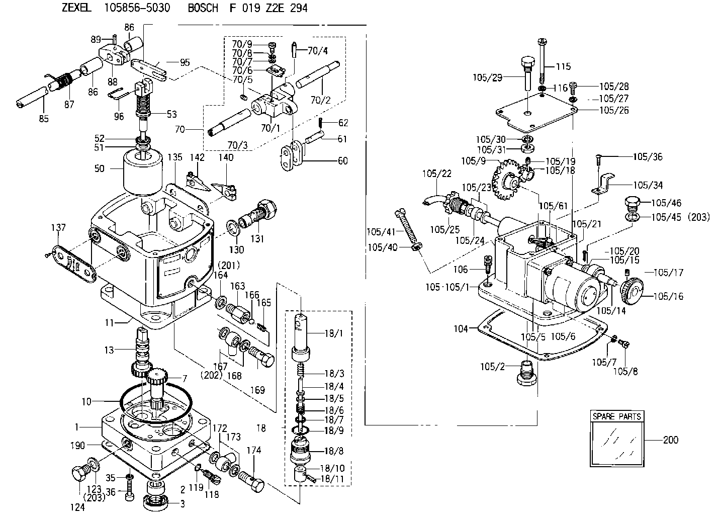
| 1. | [1] | 158502-0420 | BASE |
| 2. | [1] | 029811-8000 | BEARING PLATE |
| 3. | [1] | 158528-0900 | PACKING RING |
| 7. | [1] | 158131-0100 | GEAR SHAFT |
| 10. | [1] | 158028-0000 | O-RING |
| 11. | [1] | 158507-1120 | DIAPHRAGM HOUSING |
| 13. | [1] | 158621-0600 | SLIDING PIECE |
| 18. | [1] | 158699-0521 | COMPENSATOR ASSY |
| 18/1. | [1] | 158610-0901 | POWER PISTON |
| 18/3. | [1] | 158654-1000 | COILED SPRING |
| 18/4. | [1] | 158614-0300 | STOP PIN |
| 18/5. | [1] | 158612-0500 | PLAIN WASHER |
| 18/6. | [1] | 158654-1100 | COILED SPRING |
| 18/7. | [1] | 016110-1220 | LOCKING WASHER |
| 18/8. | [1] | 158612-0001 | BUSHING |
| 18/9. | [2] | 158528-1300 | O-RING |
| 18/10. | [1] | 158615-0400 | PUMP PLUNGER |
| 18/11. | [1] | 025620-1410 | SPRING PIN |
| 35. | [3] | 029330-6070 | GASKET |
| 36. | [3] | 010206-2520 | HEX-SOCKET-HEAD CAP SCREW |
| 50. | [1] | 158600-0720 | FLYWEIGHT ASSEMBLY |
| 51. | [1] | 158106-0100 | PLAIN WASHER |
| 52. | [1] | 029811-0000 | BEARING PLATE |
| 53. | [1] | 158620-1120 | PILOT VALVE |
| 60. | [2] | 158220-0000 | GUIDE LEVER |
| 61. | [2] | 158736-0200 | BEARING PIN |
| 62. | [4] | 025520-1510 | SPLIT PIN |
| 70. | [1] | 158730-0220 | TERMINAL ARM |
| 70/1. | [1] | 158230-0020 | TERMINAL ARM |
| 70/2. | [1] | 158315-0200 | TERMINAL SHAFT |
| 70/3. | [1] | 158315-0200 | TERMINAL SHAFT |
| 70/4. | [2] | 158736-0100 | TAPER PIN |
| 70/5. | [2] | 011006-0620 | SET OF NUTS |
| 70/6. | [1] | 158214-0020 | SPEED DROOP ADJUSTER |
| 70/7. | [1] | 014020-5120 | PLAIN WASHER |
| 70/8. | [1] | 029320-5030 | TAB WASHER |
| 70/9. | [1] | 010535-1220 | FLAT-HEAD SCREW |
| 85. | [1] | 158814-0900 | SPEED CONTROL SHAFT |
| 86. | [2] | 158823-0300 | BUSHING |
| 86. | [2] | 158823-0300 | BUSHING |
| 87. | [1] | 158322-0200 | COILED SPRING |
| 88. | [1] | 158710-0400 | STRAP |
| 89. | [1] | 029404-5010 | BEARING PIN |
| 95. | [1] | 158211-0100 | STRAP |
| 96. | [2] | 158653-0100 | WIRE |
| 104. | [1] | 158017-0900 | GASKET |
| 105. | [1] | 158963-3120 | GOVERNOR MOTOR ASSY |
| 105/1. | [1] | 158962-5110 | CASE |
| 105/2. | [1] | 158903-1920 | SCREW |
| 105/5. | [1] | 158908-3700 | GEAR HEAD |
| 105/6. | [1] | 158901-7301 | MOTOR |
| 105/7. | [4] | 014020-4140 | PLAIN WASHER D8&4.5T0.5 |
| 105/8. | [4] | 158901-8100 | FLAT-HEAD SCREW |
| 105/9. | [1] | 158402-3020 | FRICTION COUPLING |
| 105/14. | [1] | 158404-1000 | LEVER SHAFT |
| 105/15. | [2] | 014020-8140 | PLAIN WASHER D16&8.5T1.2 |
| 105/16. | [1] | 158904-1120 | ROUND NUT |
| 105/17. | [1] | 158916-0000 | SET OF NUTS |
| 105/18. | [1] | 158404-1100 | TOOTHED GEAR |
| 105/19. | [2] | 011005-0820 | SET OF NUTS |
| 105/20. | [2] | 015320-1540 | SPLIT PIN |
| 105/21. | [1] | 158401-6400 | HOSE |
| 105/22. | [1] | 158401-5000 | WIRE |
| 105/23. | [2] | 158401-7300 | GASKET |
| 105/24. | [1] | 158401-7500 | GASKET |
| 105/25. | [1] | 158401-7400 | GROUND |
| 105/26. | [1] | 158962-6100 | COVER |
| 105/27. | [3] | 014110-5440 | LOCKING WASHER |
| 105/28. | [3] | 012155-1240 | FLAT-HEAD SCREW M5P0.8L12 |
| 105/29. | [1] | 158905-0000 | FILLER PIECE |
| 105/30. | [1] | 014110-8440 | LOCKING WASHER |
| 105/31. | [1] | 013020-8140 | UNION NUT M8P1.25H6.5 |
| 105/34. | [1] | 158906-1400 | CLAMP |
| 105/36. | [1] | 012154-0840 | FLAT-HEAD SCREW M4P0.7L8 |
| 105/37. | [1] | 014110-4440 | LOCKING WASHER |
| 105/40. | [1] | 013020-6040 | UNION NUT M6P1H5 |
| 105/41. | [1] | 158067-0100 | SET OF NUTS |
| 105/45. | [1] | 026512-1640 | GASKET D15.9&12.2T1 |
| 105/46. | [1] | 029111-2070 | CAPSULE M12P1.5L10 |
| 105/61. | [2] | 158950-0100 | TERMINAL |
| 106. | [3] | 029010-6350 | BLEEDER SCREW M6P1.0L22 |
| 115. | [1] | 029050-6310 | BLEEDER SCREW |
| 116. | [1] | 014110-6440 | LOCKING WASHER |
| 118. | [1] | 158527-0200 | NEEDLE VALVE |
| 119. | [1] | 016500-0710 | O-RING |
| 123. | [2] | 026512-1640 | GASKET D15.9&12.2T1 |
| 124. | [2] | 029111-2070 | CAPSULE M12P1.5L10 |
| 130. | [1] | 029331-8040 | GASKET |
| 131. | [1] | 158660-0420 | CONTROL VALVE |
| 135. | [1] | 158515-0700 | INDICATOR PLATE |
| 137. | [1] | 158515-0800 | INDICATOR PLATE |
| 140. | [1] | 158820-0620 | POINTER |
| 142. | [1] | 158820-0620 | POINTER |
| 163. | [1] | 158522-0000 | CONNECTOR |
| 164. | [1] | 026510-1340 | GASKET D13.4&10.2T1 |
| 165. | [1] | 158655-0000 | COILED SPRING |
| 166. | [1] | 029820-6010 | BALL |
| 167. | [2] | 026512-1840 | GASKET D17.9&12.2T1.50 |
| 168. | [1] | 029701-2030 | INLET UNION |
| 169. | [1] | 158521-0000 | EYE BOLT |
| 172. | [2] | 026512-1640 | GASKET D15.9&12.2T1 |
| 173. | [1] | 029701-2030 | INLET UNION |
| 174. | [1] | 027412-2440 | EYE BOLT |
| 190. | [1] | 158017-1000 | GASKET |
| 200. | [1] | 158599-7120 | SPARE PART |
| 201. | [1] | 026510-1340 | GASKET D13.4&10.2T1 |
| 202. | [2] | 026512-1840 | GASKET D17.9&12.2T1.50 |
| 203. | [2] | 026512-1640 | GASKET D15.9&12.2T1 |
| 203. | [2] | 026512-1640 | GASKET D15.9&12.2T1 |
Include in #2:
105856-5030
as INJECTION-PUMP ASSEMBLY
Cross reference number
Zexel num
Bosch num
Firm num
Name
105856-5030
F 019 Z2E 294
HYDRAULIC GOVERNOR
* K
* K
Information:
Make reference to Guideline For Reusable Parts; Pistons, Form No. SEBF8049; Cylinder Liners, Form No. SEBF8068; and Piston Pins And Retaining Rings, Form No. SEBF8051. For installation, number on tab groove side of connecting rod is to be positioned toward opposite side of engine from camshaft.Top And Intermediate Ring
The 8T3150 Keystone Piston Ring Groove Gauge is necessary for measuring ring grooves in keystone style pistons. For correct use of the gauge group, see the instruction card that is with the gauge group.Install piston rings with "UP" side toward top of piston.(1) Top Ring has the mark "UP-1."(2) Intermediate ring has the mark "UP-2".Clearance between ends of piston ring when installed in a cylinder liner with a bore size of 137.16 mm (5.400 in):Top ring ... 0.724 0.190 mm (.0285 .0075 in)Intermediate ring ... 1.080 0.190 mm (.0425 .0075 in)Increase in clearance between ends of piston rings for each 0.03 mm (.001 in) increase in cylinder liner bore size ... 0.08 mm (.003 in)Oil Control Ring
(3) Install oil control ring with the gap in the spring 180° away from the gap in the ring. White portion of spring must be visible at the ring end gap.Width of groove in piston for piston ring (new) ... 3.210 0.013 mm (.1255 .0005 in)Thickness of piston ring (new) ... 3.137 0.013 mm (.1235 .0005 in)Clearance between groove and piston ring (new) ... 0.051 0.025 mm (.0020 .0010 in)Maximum permissible clearance (worn) ... 0.15 mm (.006 in)Clearance between ends of piston ring when installed in a cylinder liner with a bore size of 137.16 mm (5.400 in) ... 0.572 0.190 mm (.0225 .0075 in)Increase in clearance between ends of piston ring for each 0.03 mm (.001 in) increase in cylinder liner bore size ... 0.08 mm (.0003 in)Piston Pin Bore
(4) Bore in piston for pin. 1991 Model with elliptical pin bore (310 - 425 hp) Vertical ... 50.814 0.004 mm (2.0005 .0001 in)Horizontal ... actual vertical diameter plus0.032 to .048 mm (.0012 to .0019 in)Clearance between pin and bore in piston ... 0.010 to 0.028 mm (.0004 to .0011 in)Permissible clearance (worn) ... 0.05 mm (.002 in)Pin diameter ... 50.795 0.005 mm (1.9998 .0002 in) Low Crevice Volume and Gallery Pistons Bore in piston for pin ... 50.814 0.004 mm (2.0005 .0001 in)Clearance between pin and bore in piston ... 0.010 to 0.028 mm (.0004 to .0011 in)Permissible clearance (worn) ... 0.05 mm (.002 in)Pin diameter ... 50.795 0.005 mm (1.9998 .0002 in)All Other Pistons Bore in piston for pin ... 50.815 0.008 mm (2.0006 .0003 in)Clearance between pin and bore in piston ... 0.007 to 0.032 mm (.0003 to .0013 in)Permissible clearance (worn) ... 0.05 mm (.002 in)Pin diameter ... 50.795 0.005 mm (1.9998 .0002 in)
Have questions with 105856-5030?
Group cross 105856-5030 ZEXEL
Yanmar
105856-5030
F 019 Z2E 294
HYDRAULIC GOVERNOR