Information hydraulic governor
BOSCH
F 019 Z2E 293
f019z2e293
ZEXEL
105856-5020
1058565020
Rating:
Components :
| 0. | INJECTION-PUMP ASSEMBLY | 105856-5020 |
| 1. | _ | |
| 2. | FUEL INJECTION PUMP | |
| 3. | NUMBER PLATE | |
| 4. | _ | |
| 5. | CAPSULE | |
| 6. | ADJUSTING DEVICE | |
| 7. | NOZZLE AND HOLDER ASSY | |
| 8. | Nozzle and Holder | |
| 9. | Open Pre:MPa(Kqf/cm2) | |
| 10. | NOZZLE-HOLDER | |
| 11. | NOZZLE |
Scheme ###:
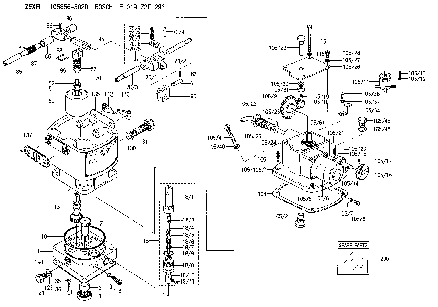
| 1. | [1] | 158502-0420 | BASE |
| 2. | [1] | 029811-8000 | BEARING PLATE |
| 3. | [1] | 158528-0900 | PACKING RING |
| 7. | [1] | 158131-0100 | GEAR SHAFT |
| 10. | [1] | 158028-0000 | O-RING |
| 11. | [1] | 158507-1820 | DIAPHRAGM HOUSING |
| 13. | [1] | 158621-0600 | SLIDING PIECE |
| 18. | [1] | 158699-0521 | COMPENSATOR ASSY |
| 18/1. | [1] | 158610-0901 | POWER PISTON |
| 18/3. | [1] | 158654-1000 | COILED SPRING |
| 18/4. | [1] | 158614-0300 | STOP PIN |
| 18/5. | [1] | 158612-0500 | PLAIN WASHER |
| 18/6. | [1] | 158654-1100 | COILED SPRING |
| 18/7. | [1] | 016110-1220 | LOCKING WASHER |
| 18/8. | [1] | 158612-0001 | BUSHING |
| 18/9. | [2] | 158528-1300 | O-RING |
| 18/10. | [1] | 158615-0400 | PUMP PLUNGER |
| 18/11. | [1] | 025620-1410 | SPRING PIN |
| 35. | [3] | 029330-6070 | GASKET |
| 36. | [3] | 010206-2520 | HEX-SOCKET-HEAD CAP SCREW |
| 50. | [1] | 158600-1020 | FLYWEIGHT ASSEMBLY |
| 51. | [1] | 158106-0100 | PLAIN WASHER |
| 52. | [1] | 029811-0000 | BEARING PLATE |
| 53. | [1] | 158620-1220 | PILOT VALVE |
| 60. | [2] | 158220-0000 | GUIDE LEVER |
| 61. | [2] | 158736-0200 | BEARING PIN |
| 62. | [4] | 025520-1510 | SPLIT PIN |
| 70. | [1] | 158730-0220 | TERMINAL ARM |
| 70/1. | [1] | 158230-0020 | TERMINAL ARM |
| 70/2. | [1] | 158315-0200 | TERMINAL SHAFT |
| 70/3. | [1] | 158315-0200 | TERMINAL SHAFT |
| 70/4. | [2] | 158736-0100 | TAPER PIN |
| 70/5. | [2] | 011006-0620 | SET OF NUTS |
| 70/6. | [1] | 158214-0020 | SPEED DROOP ADJUSTER |
| 70/7. | [1] | 014020-5120 | PLAIN WASHER |
| 70/8. | [1] | 029320-5030 | TAB WASHER |
| 70/9. | [1] | 010535-1220 | FLAT-HEAD SCREW |
| 85. | [1] | 158814-0900 | SPEED CONTROL SHAFT |
| 86. | [2] | 158823-0300 | BUSHING |
| 86. | [2] | 158823-0300 | BUSHING |
| 87. | [1] | 158322-0200 | COILED SPRING |
| 88. | [1] | 158710-0400 | STRAP |
| 89. | [1] | 029404-5010 | BEARING PIN |
| 95. | [1] | 158211-0100 | STRAP |
| 96. | [2] | 158653-0100 | WIRE |
| 104. | [1] | 158017-0900 | GASKET |
| 105. | [1] | 158562-1420 | GOVERNOR MOTOR ASSY |
| 105/1. | [1] | 158962-5110 | CASE |
| 105/2. | [1] | 158903-1920 | SCREW |
| 105/5. | [1] | 158908-3600 | GEAR HEAD |
| 105/6. | [1] | 158908-4200 | MOTOR |
| 105/7. | [4] | 014020-4140 | PLAIN WASHER D8&4.5T0.5 |
| 105/8. | [4] | 158901-8100 | FLAT-HEAD SCREW |
| 105/9. | [1] | 158402-3020 | FRICTION COUPLING |
| 105/11. | [1] | 158908-3900 | CONDENSER |
| 105/12. | [2] | 014110-3440 | LOCKING WASHER |
| 105/13. | [2] | 012153-0840 | FLAT-HEAD SCREW M3P0.5L8 |
| 105/14. | [1] | 158404-1000 | LEVER SHAFT |
| 105/15. | [2] | 014020-8140 | PLAIN WASHER D16&8.5T1.2 |
| 105/16. | [1] | 158904-1920 | ROUND NUT |
| 105/17. | [1] | 158916-0000 | SET OF NUTS |
| 105/18. | [1] | 158404-1100 | TOOTHED GEAR |
| 105/19. | [2] | 011005-0820 | SET OF NUTS |
| 105/20. | [2] | 015320-1540 | SPLIT PIN |
| 105/21. | [1] | 158401-6400 | HOSE |
| 105/22. | [1] | 158401-5000 | WIRE |
| 105/23. | [2] | 158401-7300 | GASKET |
| 105/24. | [1] | 158401-7500 | GASKET |
| 105/25. | [1] | 158401-7400 | GROUND |
| 105/26. | [1] | 158962-6100 | COVER |
| 105/27. | [3] | 014110-5440 | LOCKING WASHER |
| 105/28. | [3] | 012155-1240 | FLAT-HEAD SCREW M5P0.8L12 |
| 105/29. | [1] | 158905-0000 | FILLER PIECE |
| 105/30. | [1] | 014110-8440 | LOCKING WASHER |
| 105/31. | [1] | 013020-8140 | UNION NUT M8P1.25H6.5 |
| 105/34. | [1] | 158906-1800 | CLAMP |
| 105/36. | [1] | 012154-1040 | FLAT-HEAD SCREW M4P0.7L10 |
| 105/37. | [1] | 014110-4440 | LOCKING WASHER |
| 105/40. | [1] | 013020-6040 | UNION NUT M6P1H5 |
| 105/41. | [1] | 158067-0100 | SET OF NUTS |
| 105/45. | [1] | 026512-1640 | GASKET D15.9&12.2T1 |
| 105/46. | [1] | 029111-2070 | CAPSULE M12P1.5L10 |
| 105/61. | [1] | 158950-0100 | TERMINAL |
| 105/120. | [1] | 158908-5100 | CABLE TIE |
| 106. | [3] | 029010-6350 | BLEEDER SCREW M6P1.0L22 |
| 115. | [1] | 029050-6310 | BLEEDER SCREW |
| 116. | [1] | 014110-6440 | LOCKING WASHER |
| 118. | [1] | 158527-0200 | NEEDLE VALVE |
| 119. | [1] | 016500-0710 | O-RING |
| 123. | [2] | 026512-1640 | GASKET D15.9&12.2T1 |
| 124. | [2] | 029111-2070 | CAPSULE M12P1.5L10 |
| 130. | [1] | 029331-8040 | GASKET |
| 131. | [1] | 158660-0320 | CONTROL VALVE |
| 135. | [1] | 158515-0700 | INDICATOR PLATE |
| 137. | [1] | 158515-0800 | INDICATOR PLATE |
| 140. | [1] | 158820-0620 | POINTER |
| 142. | [1] | 158820-0620 | POINTER |
| 190. | [1] | 158017-1000 | GASKET |
| 200. | [1] | 158599-6720 | SPARE PART |
Include in #2:
105856-5020
as INJECTION-PUMP ASSEMBLY
Cross reference number
Zexel num
Bosch num
Firm num
Name
105856-5020
F 019 Z2E 293
HYDRAULIC GOVERNOR
* K 35AA Hydraulic RHD6 Others
* K 35AA Hydraulic RHD6 Others
Information:
(1) Thickness of spacer plate ... 8.585 0.025 mm (.3379 .0009 in)Thickness of gasket that is placed between spacer plate and cylinder block ... 0.208 0.025 mm (.0081 .0009 in)Height of liner over spacer plate, under installation pressure ... 0.13 0.08 mm (.005 .003 in)(2) Height of four dowels above top surface of cylinder block:End dowels (Put 7M7456 Bearing Mount Compound on two end dowels at installation) ... 18.5 0.5 mm (.73 .02 in)Middle dowels ... 16.0 0.5 mm (.63 .02 in)(3) Dimension (new) from centerline of crankshaft bearing bore to top of block (top deck) ... 425.45 0.15 mm (16.750 .006 in)Minimum dimension from centerline of crankshaft bearing bore to top of block (top deck) ... 425.02 mm (16.733 in) The flatness across the whole contact surface of the block must be within 0.10 mm (.004 in) and within 0.05 mm (.002 in) for any 177 mm (7.0 in) section of the surface. The surface finish specification is 3.2 micrometers (125 micro-inches) maximum.(4) Bore in block for camshaft bearings ... 76.835 0.018 mm (3.0250 .0007 in) Install bearings with the oil holes in the bearings on the horizontal centerline. Make sure the bearing joint position is above the oil holes.(5) Bore in the block for the main bearings:Standard, original size (new) ... 129.891 0.013 mm (5.1138 .0005 in)0.64 mm (.025 in) larger than original size ... 130.526 0.013 mm (5.1388 .0005 in)(6) Distance from front of rear face of cylinder block to end of dowels ... 19.1 0.05 mm (.75 .02 in)(7) Width of main bearing cap ... 215.900 0.013 mm (8.5000 .0005 in)Width of block for main bearing cap ... 215.900 0.013 mm (8.5000 .0005 in)Clearance between main bearing cap and cylinder block ... 0.025 mm (.0009 in) tight to 0.025 mm (.0009 in) loose
Tightening Procedure For Main Bearings(8) Torque for the bolts that hold the caps for the main bearings: Install the main bearing caps with the marks (arrow) toward the front of the engine. Install each cap in the correct position by putting the number stamped on the bottom of the cap toward the corresponding number cast on left side of the cylinder block at the pan rail.a. Put 2P2506 Thread Lubricant on the threads of the bolts.b. Tighten the bolts first on the bearing tab side of the cap to ... 260 14 N m (190 10 lb ft)c. Tighten the bolts on the opposite side to ... 260 14 N m (190 10 lb ft)d. Put a mark on each bolt and cap.e. Tighten the bolts on the opposite side, from the mark ... 120 5°f. Tighten the bolts on the bearing tab side of the cap, from the mark ... 120 5°(9) Dimension (new) from centerline of crankshaft bearing bore to bottom of block (pan rails) ... 165.10 0.10 mm
Tightening Procedure For Main Bearings(8) Torque for the bolts that hold the caps for the main bearings: Install the main bearing caps with the marks (arrow) toward the front of the engine. Install each cap in the correct position by putting the number stamped on the bottom of the cap toward the corresponding number cast on left side of the cylinder block at the pan rail.a. Put 2P2506 Thread Lubricant on the threads of the bolts.b. Tighten the bolts first on the bearing tab side of the cap to ... 260 14 N m (190 10 lb ft)c. Tighten the bolts on the opposite side to ... 260 14 N m (190 10 lb ft)d. Put a mark on each bolt and cap.e. Tighten the bolts on the opposite side, from the mark ... 120 5°f. Tighten the bolts on the bearing tab side of the cap, from the mark ... 120 5°(9) Dimension (new) from centerline of crankshaft bearing bore to bottom of block (pan rails) ... 165.10 0.10 mm
Have questions with 105856-5020?
Group cross 105856-5020 ZEXEL
Yanmar
105856-5020
F 019 Z2E 293
HYDRAULIC GOVERNOR