Information hydraulic governor
BOSCH
F 019 Z2E 290
f019z2e290
ZEXEL
105856-4650
1058564650
Rating:
Components :
| 0. | INJECTION-PUMP ASSEMBLY | 105856-4650 |
| 1. | _ | |
| 2. | FUEL INJECTION PUMP | |
| 3. | NUMBER PLATE | |
| 4. | _ | |
| 5. | CAPSULE | |
| 6. | ADJUSTING DEVICE | |
| 7. | NOZZLE AND HOLDER ASSY | |
| 8. | Nozzle and Holder | |
| 9. | Open Pre:MPa(Kqf/cm2) | |
| 10. | NOZZLE-HOLDER | |
| 11. | NOZZLE |
Scheme ###:
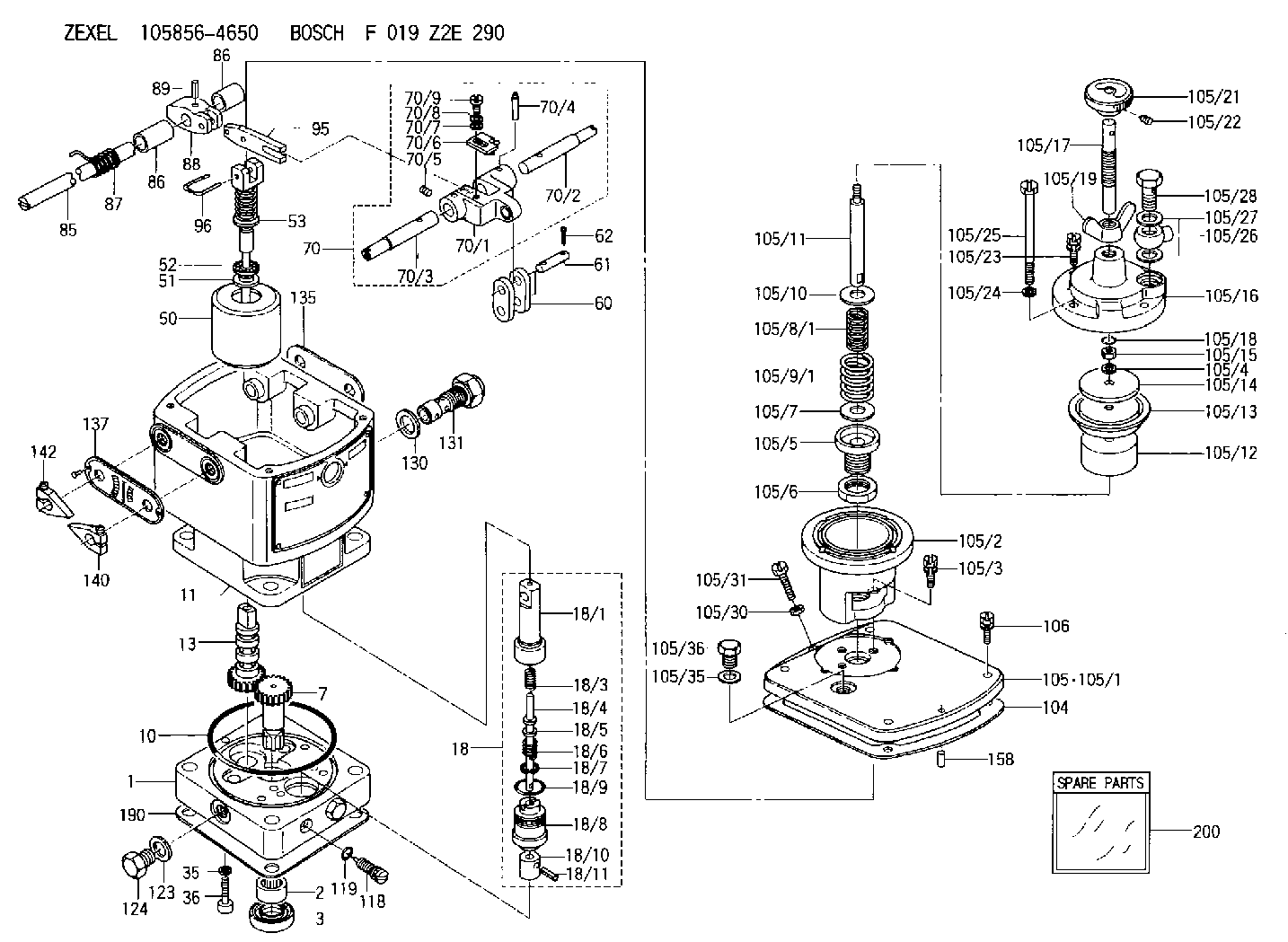
| 1. | [1] | 158502-0420 | BASE |
| 2. | [1] | 029811-8000 | BEARING PLATE |
| 3. | [1] | 158528-0900 | PACKING RING |
| 7. | [1] | 158131-0100 | GEAR SHAFT |
| 10. | [1] | 158028-0000 | O-RING |
| 11. | [1] | 158507-1820 | DIAPHRAGM HOUSING |
| 13. | [1] | 158621-0600 | SLIDING PIECE |
| 18. | [1] | 158699-0521 | COMPENSATOR ASSY |
| 18/1. | [1] | 158610-0901 | POWER PISTON |
| 18/3. | [1] | 158654-1000 | COILED SPRING |
| 18/4. | [1] | 158614-0300 | STOP PIN |
| 18/5. | [1] | 158612-0500 | PLAIN WASHER |
| 18/6. | [1] | 158654-1100 | COILED SPRING |
| 18/7. | [1] | 016110-1220 | LOCKING WASHER |
| 18/8. | [1] | 158612-0001 | BUSHING |
| 18/9. | [2] | 158528-1300 | O-RING |
| 18/10. | [1] | 158615-0400 | PUMP PLUNGER |
| 18/11. | [1] | 025620-1410 | SPRING PIN |
| 35. | [3] | 029330-6070 | GASKET |
| 36. | [3] | 010206-2520 | HEX-SOCKET-HEAD CAP SCREW |
| 50. | [1] | 158600-0720 | FLYWEIGHT ASSEMBLY |
| 51. | [1] | 158106-0100 | PLAIN WASHER |
| 52. | [1] | 029811-0000 | BEARING PLATE |
| 53. | [1] | 158620-1220 | PILOT VALVE |
| 60. | [2] | 158220-0000 | GUIDE LEVER |
| 61. | [2] | 158736-0200 | BEARING PIN |
| 62. | [4] | 025520-1510 | SPLIT PIN |
| 70. | [1] | 158730-0220 | TERMINAL ARM |
| 70/1. | [1] | 158230-0020 | TERMINAL ARM |
| 70/2. | [1] | 158315-0200 | TERMINAL SHAFT |
| 70/3. | [1] | 158315-0200 | TERMINAL SHAFT |
| 70/4. | [2] | 158736-0100 | TAPER PIN |
| 70/5. | [2] | 011006-0620 | SET OF NUTS |
| 70/6. | [1] | 158214-0020 | SPEED DROOP ADJUSTER |
| 70/7. | [1] | 014020-5120 | PLAIN WASHER |
| 70/8. | [1] | 029320-5030 | TAB WASHER |
| 70/9. | [1] | 010535-1220 | FLAT-HEAD SCREW |
| 85. | [1] | 158814-0900 | SPEED CONTROL SHAFT |
| 86. | [2] | 158823-0300 | BUSHING |
| 86. | [2] | 158823-0300 | BUSHING |
| 87. | [1] | 158322-0200 | COILED SPRING |
| 88. | [1] | 158710-0400 | STRAP |
| 89. | [1] | 029404-5010 | BEARING PIN |
| 95. | [1] | 158211-0100 | STRAP |
| 96. | [2] | 158653-0100 | WIRE |
| 104. | [1] | 158017-0900 | GASKET |
| 105. | [1] | 158964-3420 | PNEUMATIC CONTROLLER |
| 105/1. | [1] | 158562-4600 | COVER |
| 105/2. | [1] | 158910-0200 | CYLINDER |
| 105/3. | [3] | 029050-6090 | FLAT-HEAD SCREW |
| 105/4. | [1] | 014110-6440 | LOCKING WASHER |
| 105/5. | [1] | 158416-0000 | FLAT-HEAD SCREW |
| 105/6. | [1] | 158915-0700 | UNION NUT |
| 105/7. | [1] | 158918-0000 | PLAIN WASHER D30&10.8T1.00 |
| 105/8/1. | [1] | 158412-0100 | COILED SPRING K1.0 |
| 105/8/1. | [1] | 158412-0200 | COILED SPRING K2.0 |
| 105/8/1. | [1] | 158412-0300 | COILED SPRING K3.0 |
| 105/8/1. | [1] | 158412-0400 | COILED SPRING K4.0 |
| 105/8/1. | [1] | 158412-0500 | COILED SPRING K5.0 |
| 105/8/1. | [1] | 158912-1800 | COILED SPRING K3.4 |
| 105/8/1. | [1] | 158912-1900 | COILED SPRING K2.5 |
| 105/8/1. | [1] | 158912-3300 | COILED SPRING K4.5 |
| 105/9/1. | [1] | 158412-0000 | COILED SPRING K7.0 |
| 105/9/1. | [1] | 158912-0500 | COILED SPRING K4.9 |
| 105/9/1. | [1] | 158912-0600 | COILED SPRING K5.1 |
| 105/9/1. | [1] | 158912-0700 | COILED SPRING K5.2 |
| 105/9/1. | [1] | 158912-1100 | COILED SPRING K4.8 |
| 105/9/1. | [1] | 158912-1200 | COILED SPRING K5.4 |
| 105/9/1. | [1] | 158912-2300 | COILED SPRING K6.8 |
| 105/9/1. | [1] | 158912-2400 | COILED SPRING K7.0 |
| 105/9/1. | [1] | 158912-2500 | COILED SPRING K7.3 |
| 105/9/1. | [1] | 158912-2600 | COILED SPRING K7.4 |
| 105/10. | [1] | 158918-0000 | PLAIN WASHER D30&10.8T1.00 |
| 105/11. | [1] | 158413-0001 | STOP PIN |
| 105/12. | [1] | 158414-0000 | PUMP PLUNGER |
| 105/13. | [1] | 158414-0100 | DIAPHRAGM |
| 105/14. | [1] | 158414-0200 | PLATE |
| 105/15. | [1] | 013020-6040 | UNION NUT M6P1H5 |
| 105/16. | [1] | 158910-0300 | CAP |
| 105/17. | [1] | 158915-1000 | FLAT-HEAD SCREW |
| 105/18. | [1] | 029630-9050 | O-RING |
| 105/19. | [1] | 158567-1500 | WING NUT |
| 105/21. | [1] | 158904-2020 | ROUND NUT |
| 105/22. | [1] | 158916-0000 | SET OF NUTS |
| 105/23. | [2] | 029050-6220 | FLAT-HEAD SCREW |
| 105/24. | [2] | 029320-6010 | LOCKING WASHER |
| 105/25. | [2] | 158909-0200 | BLEEDER SCREW |
| 105/26. | [1] | 027114-1040 | INLET UNION |
| 105/27. | [2] | 029331-4120 | GASKET D18&14.2T1.5 |
| 105/28. | [1] | 027414-2640 | EYE BOLT |
| 105/30. | [1] | 013020-6040 | UNION NUT M6P1H5 |
| 105/31. | [1] | 158567-1200 | SET OF NUTS |
| 105/35. | [1] | 026512-1640 | GASKET D15.9&12.2T1 |
| 105/36. | [1] | 158066-0000 | BLEEDER SCREW |
| 106. | [4] | 029010-6350 | BLEEDER SCREW M6P1.0L22 |
| 118. | [1] | 158527-0200 | NEEDLE VALVE |
| 119. | [1] | 016500-0710 | O-RING |
| 123. | [2] | 026512-1640 | GASKET D15.9&12.2T1 |
| 124. | [2] | 029111-2070 | CAPSULE M12P1.5L10 |
| 130. | [1] | 029331-8040 | GASKET |
| 131. | [1] | 158660-0320 | CONTROL VALVE |
| 135. | [1] | 158515-0700 | INDICATOR PLATE |
| 137. | [1] | 158515-0800 | INDICATOR PLATE |
| 140. | [1] | 158820-0620 | POINTER |
| 142. | [1] | 158820-0620 | POINTER |
| 158. | [1] | 015040-0880 | BEARING PIN |
| 190. | [1] | 158017-1000 | GASKET |
| 200. | [1] | 158599-6920 | SPARE PART |
Include in #2:
105856-4650
as INJECTION-PUMP ASSEMBLY
Cross reference number
Zexel num
Bosch num
Firm num
Name
Information:
Before any service work is done on the fuel system, the outer surface of the injection pump housing must be clean.
Illustrations show fuel injection pump housing and governor removed from engine. Service work can be done with it installed on engine.1. Remove air bleed lines (2). 2. Remove bolts (1), flange (3), the flange assembly and the gaskets.3. Remove the bolts and the cover. 4. Remove bolts (5), solenoid (4) and the gasket.5. Remove two bolts (7) and fuel ratio control (6).6. Remove the shutoff housing from the cover. 7. Remove the bolts, lever (10) and shaft (8).8. Remove the bolts, lever (9) and shaft (11).9. Remove seal (12) from the shutoff housing. Install Shutoff Housing
1. Put 5S1454 Sealing Compound on the outside diameter of the seal and install the seal (1) with tooling (A) in the shutoff housing with the lip toward the outside. The outer face of the seal must be 1.0 mm (.039 in.) below the surface of the housing. Remove the extra sealing compound from the housing and the seal after installation. 2. Put shaft (5) in position in housing (4).3. Install lever (6) and the bolts. 4. Install shaft (2), lever (3) and the bolts. Make an alignment of the notch in shaft (2) with lever (3). 5. Put cover (7) in position on shutoff housing assembly (8) and install the bolts.6. Put fuel ratio control (10) in position and install the bolts. 7. Install the gasket, solenoid (9) and bolts on the cover.8. Put the cover in position and install the bolts.9. Install the gasket, flange assembly, gasket, flange (11) and the bolts.10. Connect air bleed lines (12).