Information hydraulic governor
BOSCH
F 019 Z2E 284
f019z2e284
ZEXEL
105856-4580
1058564580
DAIHATSU
QGDK312440FZ
qgdk312440fz
Rating:
Components :
| 0. | INJECTION-PUMP ASSEMBLY | 105856-4580 |
| 1. | _ | |
| 2. | FUEL INJECTION PUMP | |
| 3. | NUMBER PLATE | |
| 4. | _ | |
| 5. | CAPSULE | |
| 6. | ADJUSTING DEVICE | |
| 7. | NOZZLE AND HOLDER ASSY | |
| 8. | Nozzle and Holder | |
| 9. | Open Pre:MPa(Kqf/cm2) | |
| 10. | NOZZLE-HOLDER | |
| 11. | NOZZLE |
Scheme ###:
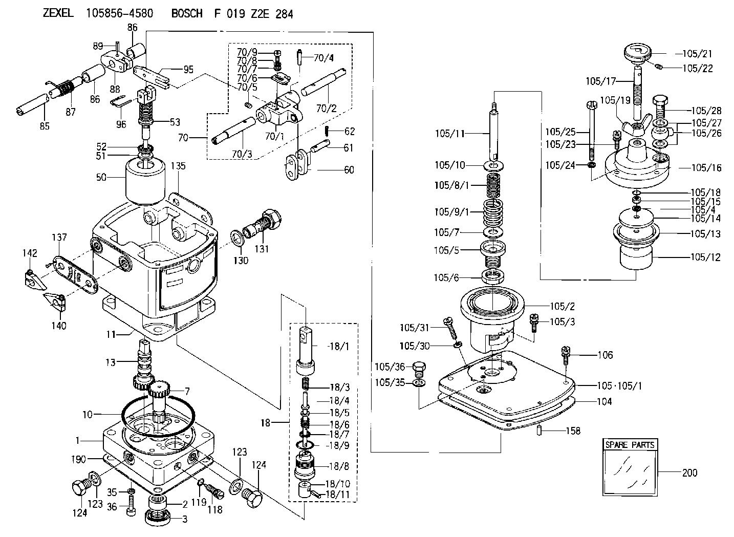
| 1. | [1] | 158502-0420 | BASE |
| 2. | [1] | 029811-8000 | BEARING PLATE |
| 3. | [1] | 158528-0900 | PACKING RING |
| 7. | [1] | 158131-0100 | GEAR SHAFT |
| 10. | [1] | 158028-0000 | O-RING |
| 11. | [1] | 158507-1820 | DIAPHRAGM HOUSING |
| 13. | [1] | 158621-0500 | SLEEVE |
| 18. | [1] | 158699-0521 | COMPENSATOR ASSY |
| 18/1. | [1] | 158610-0901 | POWER PISTON |
| 18/3. | [1] | 158654-1000 | COILED SPRING |
| 18/4. | [1] | 158614-0300 | STOP PIN |
| 18/5. | [1] | 158612-0500 | PLAIN WASHER |
| 18/6. | [1] | 158654-1100 | COILED SPRING |
| 18/7. | [1] | 016110-1220 | LOCKING WASHER |
| 18/8. | [1] | 158612-0001 | BUSHING |
| 18/9. | [2] | 158528-1300 | O-RING |
| 18/10. | [1] | 158615-0400 | PUMP PLUNGER |
| 18/11. | [1] | 025620-1410 | SPRING PIN |
| 35. | [3] | 029330-6070 | GASKET |
| 36. | [3] | 010206-2520 | HEX-SOCKET-HEAD CAP SCREW |
| 50. | [1] | 158600-1020 | FLYWEIGHT ASSEMBLY |
| 51. | [1] | 158106-0100 | PLAIN WASHER |
| 52. | [1] | 029811-0000 | BEARING PLATE |
| 53. | [1] | 158620-1220 | PILOT VALVE |
| 60. | [2] | 158220-0000 | GUIDE LEVER |
| 61. | [2] | 158736-0200 | BEARING PIN |
| 62. | [4] | 025520-1510 | SPLIT PIN |
| 70. | [1] | 158730-0220 | TERMINAL ARM |
| 70/1. | [1] | 158230-0020 | TERMINAL ARM |
| 70/2. | [1] | 158315-0200 | TERMINAL SHAFT |
| 70/3. | [1] | 158315-0200 | TERMINAL SHAFT |
| 70/4. | [2] | 158736-0100 | TAPER PIN |
| 70/5. | [2] | 011006-0620 | SET OF NUTS |
| 70/6. | [1] | 158214-0020 | SPEED DROOP ADJUSTER |
| 70/7. | [1] | 014020-5120 | PLAIN WASHER |
| 70/8. | [1] | 029320-5030 | TAB WASHER |
| 70/9. | [1] | 010535-1220 | FLAT-HEAD SCREW |
| 85. | [1] | 158814-0900 | SPEED CONTROL SHAFT |
| 86. | [2] | 158823-0300 | BUSHING |
| 86. | [2] | 158823-0300 | BUSHING |
| 87. | [1] | 158322-0200 | COILED SPRING |
| 88. | [1] | 158710-0400 | STRAP |
| 89. | [1] | 029404-5010 | BEARING PIN |
| 95. | [1] | 158211-0100 | STRAP |
| 96. | [2] | 158653-0100 | WIRE |
| 104. | [1] | 158017-0900 | GASKET |
| 105. | [1] | 158964-3420 | PNEUMATIC CONTROLLER |
| 105/1. | [1] | 158562-4600 | COVER |
| 105/2. | [1] | 158910-0200 | CYLINDER |
| 105/3. | [3] | 029050-6090 | FLAT-HEAD SCREW |
| 105/4. | [1] | 014110-6440 | LOCKING WASHER |
| 105/5. | [1] | 158416-0000 | FLAT-HEAD SCREW |
| 105/6. | [1] | 158915-0700 | UNION NUT |
| 105/7. | [1] | 158918-0000 | PLAIN WASHER D30&10.8T1.00 |
| 105/8/1. | [1] | 158412-0100 | COILED SPRING K1.0 |
| 105/8/1. | [1] | 158412-0200 | COILED SPRING K2.0 |
| 105/8/1. | [1] | 158412-0300 | COILED SPRING K3.0 |
| 105/8/1. | [1] | 158412-0400 | COILED SPRING K4.0 |
| 105/8/1. | [1] | 158412-0500 | COILED SPRING K5.0 |
| 105/8/1. | [1] | 158912-1800 | COILED SPRING K3.4 |
| 105/8/1. | [1] | 158912-1900 | COILED SPRING K2.5 |
| 105/8/1. | [1] | 158912-3300 | COILED SPRING K4.5 |
| 105/9/1. | [1] | 158412-0000 | COILED SPRING K7.0 |
| 105/9/1. | [1] | 158912-0500 | COILED SPRING K4.9 |
| 105/9/1. | [1] | 158912-0600 | COILED SPRING K5.1 |
| 105/9/1. | [1] | 158912-0700 | COILED SPRING K5.2 |
| 105/9/1. | [1] | 158912-1100 | COILED SPRING K4.8 |
| 105/9/1. | [1] | 158912-1200 | COILED SPRING K5.4 |
| 105/9/1. | [1] | 158912-2300 | COILED SPRING K6.8 |
| 105/9/1. | [1] | 158912-2400 | COILED SPRING K7.0 |
| 105/9/1. | [1] | 158912-2500 | COILED SPRING K7.3 |
| 105/9/1. | [1] | 158912-2600 | COILED SPRING K7.4 |
| 105/10. | [1] | 158918-0000 | PLAIN WASHER D30&10.8T1.00 |
| 105/11. | [1] | 158413-0001 | STOP PIN |
| 105/12. | [1] | 158414-0000 | PUMP PLUNGER |
| 105/13. | [1] | 158414-0100 | DIAPHRAGM |
| 105/14. | [1] | 158414-0200 | PLATE |
| 105/15. | [1] | 013020-6040 | UNION NUT M6P1H5 |
| 105/16. | [1] | 158910-0300 | CAP |
| 105/17. | [1] | 158915-1000 | FLAT-HEAD SCREW |
| 105/18. | [1] | 029630-9050 | O-RING |
| 105/19. | [1] | 158567-1500 | WING NUT |
| 105/21. | [1] | 158904-2020 | ROUND NUT |
| 105/22. | [1] | 158916-0000 | SET OF NUTS |
| 105/23. | [2] | 029050-6220 | FLAT-HEAD SCREW |
| 105/24. | [2] | 029320-6010 | LOCKING WASHER |
| 105/25. | [2] | 158909-0200 | BLEEDER SCREW |
| 105/26. | [1] | 027114-1040 | INLET UNION |
| 105/27. | [2] | 029331-4120 | GASKET D18&14.2T1.5 |
| 105/28. | [1] | 027414-2640 | EYE BOLT |
| 105/30. | [1] | 013020-6040 | UNION NUT M6P1H5 |
| 105/31. | [1] | 158567-1200 | SET OF NUTS |
| 105/35. | [1] | 026512-1640 | GASKET D15.9&12.2T1 |
| 105/36. | [1] | 158066-0000 | BLEEDER SCREW |
| 106. | [4] | 029010-6350 | BLEEDER SCREW M6P1.0L22 |
| 118. | [1] | 158527-0200 | NEEDLE VALVE |
| 119. | [1] | 016500-0710 | O-RING |
| 123. | [2] | 026512-1640 | GASKET D15.9&12.2T1 |
| 123. | [2] | 026512-1640 | GASKET D15.9&12.2T1 |
| 124. | [2] | 029111-2070 | CAPSULE M12P1.5L10 |
| 124. | [2] | 029111-2070 | CAPSULE M12P1.5L10 |
| 130. | [1] | 029331-8040 | GASKET |
| 131. | [1] | 158660-0320 | CONTROL VALVE |
| 135. | [1] | 158515-0700 | INDICATOR PLATE |
| 137. | [1] | 158515-0800 | INDICATOR PLATE |
| 140. | [1] | 158820-0620 | POINTER |
| 142. | [1] | 158820-0620 | POINTER |
| 158. | [1] | 015040-0880 | BEARING PIN |
| 190. | [1] | 158017-1000 | GASKET |
| 200. | [1] | 158599-6920 | SPARE PART |
Include in #2:
105856-4580
as INJECTION-PUMP ASSEMBLY
Cross reference number
Zexel num
Bosch num
Firm num
Name
Information:
White Smoke
Recommended Procedure
1. Cold Outside Temperatures ... When the air outside is cold, the cylinder temperature is cooler. Not all the fuel will burn in the cylinders. The fuel which does not burn comes out the exhaust as white smoke. White smoke is normal in cold temperatures until the engine operates long enough to become warm. There will be less white smoke if No. 1 diesel fuel is used.2. Long Idle Periods ... When an engine runs at idle speed for a long period of time, the cylinders cool and all of the fuel does not burn. Do not idle an engine for a long period of time. Stop an engine when it is not in use. If long idle periods are necessary, use No. 1 diesel fuel.3. Low Quality Fuel ... Test the engine using fuel according to recommendations by Caterpillar.4. Air in Fuel System ... With air in the fuel system the engine will normally be difficult to start, run rough and release a large amount of white smoke. To remove the air from the fuel system open the manual bleed valve on the fuel injection pump housing. Operate the priming pump until the flow of fuel from the manual bleed valve is free of air. Close the manual bleed valve and fasten the fuel priming pump. Start the engine. If the engine still does not run smooth or releases a large amount of white smoke, loosen the fuel line nuts one at a time at the cylinder heads, and permit the fuel to come out until it is free of air. Tighten the fuel line nuts. If air is not removed in this way, put 35 kPa (5 psi) of air pressure to the fuel tank.
Do not use more than 55 kPa (8 psi) of air pressure in the fuel tank or damage to the tank may result.
Check for leakage at the connections between the fuel tank and the fuel transfer pump. If leaks are found, tighten the connections or replace the lines. If there are no visual leaks, remove the fuel supply line from the tank and connect it to an outside fuel supply. If this corrects the problem, the suction line (standpipe) inside the fuel tank has a leak.5. Fuel Injection Timing Not Correct ... Check and make necessary adjustments as per Testing and Adjusting section of this Service Manual.6. Automatic Timing Advance Does Not Operate Correctly ... Check with engine warm. Use the 8T5300 Timing Indicator Group to check the automatic timing advance unit. Check to see that the advance is smooth and that the amount of advance is correct. See Fuel System of the Testing and Adjusting section of this Service Manual for the subject Checking Engine Timing And Automatic Timing Advance Unit With 8T5300 Timing Indicator Group. If the timing indicator is not available, make rapid "acceleration" (increase in speed) from low idle to high idle. Engine must have smooth acceleration. A timing advance that does not operate correctly