Information hydraulic governor
BOSCH
F 019 Z2E 280
f019z2e280
ZEXEL
105856-4540
1058564540
MATSUI-IRON
871675A5
871675a5
Rating:
Components :
| 0. | INJECTION-PUMP ASSEMBLY | 105856-4540 |
| 1. | _ | |
| 2. | FUEL INJECTION PUMP | |
| 3. | NUMBER PLATE | |
| 4. | _ | |
| 5. | CAPSULE | |
| 6. | ADJUSTING DEVICE | |
| 7. | NOZZLE AND HOLDER ASSY | |
| 8. | Nozzle and Holder | |
| 9. | Open Pre:MPa(Kqf/cm2) | |
| 10. | NOZZLE-HOLDER | |
| 11. | NOZZLE |
Scheme ###:
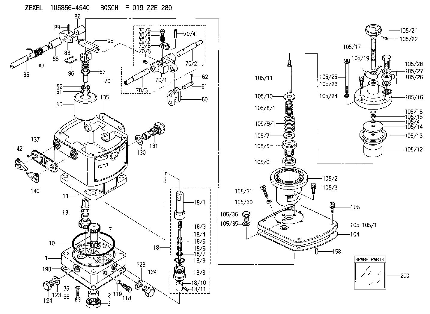
| 1. | [1] | 158502-0420 | BASE |
| 2. | [1] | 029811-8000 | BEARING PLATE |
| 3. | [1] | 158528-0900 | PACKING RING |
| 7. | [1] | 158131-0100 | GEAR SHAFT |
| 10. | [1] | 158028-0000 | O-RING |
| 11. | [1] | 158507-1820 | DIAPHRAGM HOUSING |
| 13. | [1] | 158621-0500 | SLEEVE |
| 18. | [1] | 158699-0321 | COMPENSATOR ASSY |
| 18/1. | [1] | 158610-0901 | POWER PISTON |
| 18/3. | [1] | 158654-0400 | COILED SPRING |
| 18/4. | [1] | 158614-0300 | STOP PIN |
| 18/5. | [1] | 158612-0500 | PLAIN WASHER |
| 18/6. | [1] | 158654-0500 | COILED SPRING |
| 18/7. | [1] | 016110-1220 | LOCKING WASHER |
| 18/8. | [1] | 158612-0001 | BUSHING |
| 18/9. | [2] | 158528-1300 | O-RING |
| 18/10. | [1] | 158615-0300 | PUMP PLUNGER |
| 18/11. | [1] | 025620-1410 | SPRING PIN |
| 35. | [3] | 029330-6070 | GASKET |
| 36. | [3] | 010206-2520 | HEX-SOCKET-HEAD CAP SCREW |
| 50. | [1] | 158600-0720 | FLYWEIGHT ASSEMBLY |
| 51. | [1] | 158106-0100 | PLAIN WASHER |
| 52. | [1] | 029811-0000 | BEARING PLATE |
| 53. | [1] | 158620-1120 | PILOT VALVE |
| 60. | [2] | 158220-0000 | GUIDE LEVER |
| 61. | [2] | 158736-0200 | BEARING PIN |
| 62. | [4] | 025520-1510 | SPLIT PIN |
| 70. | [1] | 158730-0220 | TERMINAL ARM |
| 70/1. | [1] | 158230-0020 | TERMINAL ARM |
| 70/2. | [1] | 158315-0200 | TERMINAL SHAFT |
| 70/3. | [1] | 158315-0200 | TERMINAL SHAFT |
| 70/4. | [2] | 158736-0100 | TAPER PIN |
| 70/5. | [2] | 011006-0620 | SET OF NUTS |
| 70/6. | [1] | 158214-0020 | SPEED DROOP ADJUSTER |
| 70/7. | [1] | 014020-5120 | PLAIN WASHER |
| 70/8. | [1] | 029320-5030 | TAB WASHER |
| 70/9. | [1] | 010535-1220 | FLAT-HEAD SCREW |
| 85. | [1] | 158814-0900 | SPEED CONTROL SHAFT |
| 86. | [2] | 158823-0300 | BUSHING |
| 86. | [2] | 158823-0300 | BUSHING |
| 87. | [1] | 158322-0200 | COILED SPRING |
| 88. | [1] | 158710-0400 | STRAP |
| 89. | [1] | 029404-5010 | BEARING PIN |
| 95. | [1] | 158211-0100 | STRAP |
| 96. | [2] | 158653-0100 | WIRE |
| 104. | [1] | 158017-0900 | GASKET |
| 105. | [1] | 158964-3420 | PNEUMATIC CONTROLLER |
| 105/1. | [1] | 158562-4600 | COVER |
| 105/2. | [1] | 158910-0200 | CYLINDER |
| 105/3. | [3] | 029050-6090 | FLAT-HEAD SCREW |
| 105/4. | [1] | 014110-6440 | LOCKING WASHER |
| 105/5. | [1] | 158416-0000 | FLAT-HEAD SCREW |
| 105/6. | [1] | 158915-0700 | UNION NUT |
| 105/7. | [1] | 158918-0000 | PLAIN WASHER D30&10.8T1.00 |
| 105/8/1. | [1] | 158412-0100 | COILED SPRING K1.0 |
| 105/8/1. | [1] | 158412-0200 | COILED SPRING K2.0 |
| 105/8/1. | [1] | 158412-0300 | COILED SPRING K3.0 |
| 105/8/1. | [1] | 158412-0400 | COILED SPRING K4.0 |
| 105/8/1. | [1] | 158412-0500 | COILED SPRING K5.0 |
| 105/8/1. | [1] | 158912-1800 | COILED SPRING K3.4 |
| 105/8/1. | [1] | 158912-1900 | COILED SPRING K2.5 |
| 105/8/1. | [1] | 158912-3300 | COILED SPRING K4.5 |
| 105/9/1. | [1] | 158412-0000 | COILED SPRING K7.0 |
| 105/9/1. | [1] | 158912-0500 | COILED SPRING K4.9 |
| 105/9/1. | [1] | 158912-0600 | COILED SPRING K5.1 |
| 105/9/1. | [1] | 158912-0700 | COILED SPRING K5.2 |
| 105/9/1. | [1] | 158912-1100 | COILED SPRING K4.8 |
| 105/9/1. | [1] | 158912-1200 | COILED SPRING K5.4 |
| 105/9/1. | [1] | 158912-2300 | COILED SPRING K6.8 |
| 105/9/1. | [1] | 158912-2400 | COILED SPRING K7.0 |
| 105/9/1. | [1] | 158912-2500 | COILED SPRING K7.3 |
| 105/9/1. | [1] | 158912-2600 | COILED SPRING K7.4 |
| 105/10. | [1] | 158918-0000 | PLAIN WASHER D30&10.8T1.00 |
| 105/11. | [1] | 158413-0001 | STOP PIN |
| 105/12. | [1] | 158414-0000 | PUMP PLUNGER |
| 105/13. | [1] | 158414-0100 | DIAPHRAGM |
| 105/14. | [1] | 158414-0200 | PLATE |
| 105/15. | [1] | 013020-6040 | UNION NUT M6P1H5 |
| 105/16. | [1] | 158910-0300 | CAP |
| 105/17. | [1] | 158915-1000 | FLAT-HEAD SCREW |
| 105/18. | [1] | 029630-9050 | O-RING |
| 105/19. | [1] | 158567-1500 | WING NUT |
| 105/21. | [1] | 158904-2020 | ROUND NUT |
| 105/22. | [1] | 158916-0000 | SET OF NUTS |
| 105/23. | [2] | 029050-6220 | FLAT-HEAD SCREW |
| 105/24. | [2] | 029320-6010 | LOCKING WASHER |
| 105/25. | [2] | 158909-0200 | BLEEDER SCREW |
| 105/26. | [1] | 027114-1040 | INLET UNION |
| 105/27. | [2] | 029331-4120 | GASKET D18&14.2T1.5 |
| 105/28. | [1] | 027414-2640 | EYE BOLT |
| 105/30. | [1] | 013020-6040 | UNION NUT M6P1H5 |
| 105/31. | [1] | 158567-1200 | SET OF NUTS |
| 105/35. | [1] | 026512-1640 | GASKET D15.9&12.2T1 |
| 105/36. | [1] | 158066-0000 | BLEEDER SCREW |
| 106. | [4] | 029010-6350 | BLEEDER SCREW M6P1.0L22 |
| 118. | [1] | 158027-0100 | NEEDLE VALVE |
| 119. | [1] | 016500-0710 | O-RING |
| 123. | [2] | 026512-1640 | GASKET D15.9&12.2T1 |
| 123. | [2] | 026512-1640 | GASKET D15.9&12.2T1 |
| 123. | [2] | 026512-1640 | GASKET D15.9&12.2T1 |
| 124. | [2] | 029111-2070 | CAPSULE M12P1.5L10 |
| 130. | [1] | 029331-8040 | GASKET |
| 131. | [1] | 158660-0320 | CONTROL VALVE |
| 135. | [1] | 158515-0700 | INDICATOR PLATE |
| 137. | [1] | 158515-0800 | INDICATOR PLATE |
| 140. | [1] | 158820-0620 | POINTER |
| 142. | [1] | 158820-0620 | POINTER |
| 158. | [1] | 015040-0880 | BEARING PIN |
| 190. | [1] | 158017-1000 | GASKET |
| 200. | [1] | 158599-6920 | SPARE PART |
Include in #2:
105856-4540
as INJECTION-PUMP ASSEMBLY
Cross reference number
Zexel num
Bosch num
Firm num
Name
105856-4540
871675A5 MATSUI-IRON
HYDRAULIC GOVERNOR
K 35AA HYDRAULIC GOVERNOR Hydraulic RHD6 Others
K 35AA HYDRAULIC GOVERNOR Hydraulic RHD6 Others
Information:
1. Fuel consumption records must be available before the high fuel consumption complaint can be verified. If symptoms indicate low power, then the low power test should be conducted first, because it could be the cause of the fuel consumption problem. This Primary Engine Test for High Fuel Consumption is the same as the Primary Engine Test for Low Power.2. Visually inspect the fuel system from the fuel tank to the fuel injection lines to see if there are any indications of fuel leaks. Tighten any loose connections found and, if necessary, replace lines that can not be repaired.3. Check the crankcase oil level and the coolant level of the radiator. Start the engine and get to normal operating temperature. A slightly lower rpm (15 rpm below low limit) should be expected for the engine in vehicle than the rpm shown in the Fuel Setting And Related Information Fiche. This is caused by the parasitic loads of the engine accessories involved.4. With the engine running, the throttle must have enough travel for the governor control lever to break over (go past the normal governor stop for high idle position) a small amount when the throttle pedal is fully depressed. If full travel is not available, disconnect throttle linkage from governor lever. With throttle linkage disconnected, full travel of governor lever will indicate linkage problems, and the linkage will have to be adjusted. Limited travel of the governor lever will indicate a problem within the governor.5. Only a mechanic with the correct training should change the set point (balance point) adjustment. The procedure is given in this Service Manual under the subject Governor Adjustments.6. If high idle rpm can not be made correct with the high idle adjustment screw, there is a problem inside the governor. Disassemble the governor and check for damaged parts or wrong parts installed in the governor. Some common problems are worn bushings, worn spring seat, or a broken or wrong governor spring.7. Before 8T0500 Circuit Tester is installed, be sure to test the light for correct operation. Test ligh must come on when the clip of the wire is placed against the probe of the light (replace batteries or bulb if light does not come on). If light comes on and stays on when attached to governor, the insulation is bad or installed wrong in torque spring group or brass terminal. This must be corrected before test is performed.8. With the continuity light installed, quickly push accelerator pedal all the way to the floor. If the fuel control shaft and governor function properly, the continuity light will come on during this free acceleration until high idle is maintained.If the light comes on, this is an indication that the mechanical movement of the governor and fuel injection pump parts operate properly. The fuel setting should now be checked. If the light does not come on during free acceleration, check for a problem inside the governor.9. Install 5P4203 Field Service Tool Group, and check the