Information hydraulic governor
BOSCH
F 019 Z2E 276
f019z2e276
ZEXEL
105856-4500
1058564500
Rating:
Components :
| 0. | INJECTION-PUMP ASSEMBLY | 105856-4500 |
| 1. | _ | |
| 2. | FUEL INJECTION PUMP | |
| 3. | NUMBER PLATE | |
| 4. | _ | |
| 5. | CAPSULE | |
| 6. | ADJUSTING DEVICE | |
| 7. | NOZZLE AND HOLDER ASSY | |
| 8. | Nozzle and Holder | |
| 9. | Open Pre:MPa(Kqf/cm2) | |
| 10. | NOZZLE-HOLDER | |
| 11. | NOZZLE |
Scheme ###:
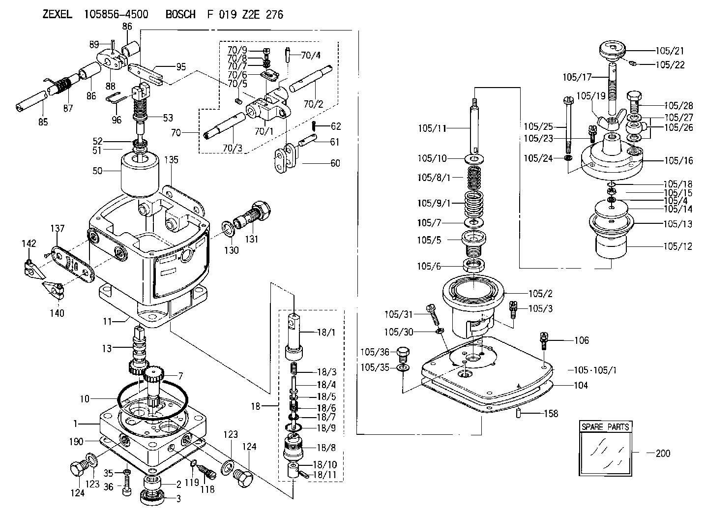
| 1. | [1] | 158502-0420 | BASE |
| 2. | [1] | 029811-8000 | BEARING PLATE |
| 3. | [1] | 158528-0900 | PACKING RING |
| 7. | [1] | 158131-0100 | GEAR SHAFT |
| 10. | [1] | 158028-0000 | O-RING |
| 11. | [1] | 158507-1820 | DIAPHRAGM HOUSING |
| 13. | [1] | 158621-0500 | SLEEVE |
| 18. | [1] | 158699-0321 | COMPENSATOR ASSY |
| 18/1. | [1] | 158610-0901 | POWER PISTON |
| 18/3. | [1] | 158654-0400 | COILED SPRING |
| 18/4. | [1] | 158614-0300 | STOP PIN |
| 18/5. | [1] | 158612-0500 | PLAIN WASHER |
| 18/6. | [1] | 158654-0500 | COILED SPRING |
| 18/7. | [1] | 016110-1220 | LOCKING WASHER |
| 18/8. | [1] | 158612-0001 | BUSHING |
| 18/9. | [2] | 158528-1300 | O-RING |
| 18/10. | [1] | 158615-0300 | PUMP PLUNGER |
| 18/11. | [1] | 025620-1410 | SPRING PIN |
| 35. | [3] | 029330-6070 | GASKET |
| 36. | [3] | 010206-2520 | HEX-SOCKET-HEAD CAP SCREW |
| 50. | [1] | 158600-0720 | FLYWEIGHT ASSEMBLY |
| 51. | [1] | 158106-0100 | PLAIN WASHER |
| 52. | [1] | 029811-0000 | BEARING PLATE |
| 53. | [1] | 158620-1120 | PILOT VALVE |
| 60. | [2] | 158220-0000 | GUIDE LEVER |
| 61. | [2] | 158736-0200 | BEARING PIN |
| 62. | [4] | 025520-1510 | SPLIT PIN |
| 70. | [1] | 158730-0220 | TERMINAL ARM |
| 70/1. | [1] | 158230-0020 | TERMINAL ARM |
| 70/2. | [1] | 158315-0200 | TERMINAL SHAFT |
| 70/3. | [1] | 158315-0200 | TERMINAL SHAFT |
| 70/4. | [2] | 158736-0100 | TAPER PIN |
| 70/5. | [2] | 011006-0620 | SET OF NUTS |
| 70/6. | [1] | 158214-0020 | SPEED DROOP ADJUSTER |
| 70/7. | [1] | 014020-5120 | PLAIN WASHER |
| 70/8. | [1] | 029320-5030 | TAB WASHER |
| 70/9. | [1] | 010535-1220 | FLAT-HEAD SCREW |
| 85. | [1] | 158814-0900 | SPEED CONTROL SHAFT |
| 86. | [2] | 158823-0300 | BUSHING |
| 86. | [2] | 158823-0300 | BUSHING |
| 87. | [1] | 158322-0200 | COILED SPRING |
| 88. | [1] | 158710-0400 | STRAP |
| 89. | [1] | 029404-5010 | BEARING PIN |
| 95. | [1] | 158211-0100 | STRAP |
| 96. | [2] | 158653-0100 | WIRE |
| 104. | [1] | 158017-0900 | GASKET |
| 105. | [1] | 158964-5120 | PNEUMATIC CONTROLLER |
| 105/1. | [1] | 158562-4600 | COVER |
| 105/2. | [1] | 158910-0200 | CYLINDER |
| 105/3. | [3] | 029050-6090 | FLAT-HEAD SCREW |
| 105/4. | [1] | 014110-6440 | LOCKING WASHER |
| 105/5. | [1] | 158416-0000 | FLAT-HEAD SCREW |
| 105/6. | [1] | 158915-0700 | UNION NUT |
| 105/7. | [1] | 158918-0000 | PLAIN WASHER D30&10.8T1.00 |
| 105/8/1. | [1] | 158412-0100 | COILED SPRING K1.0 |
| 105/8/1. | [1] | 158412-0200 | COILED SPRING K2.0 |
| 105/8/1. | [1] | 158412-0300 | COILED SPRING K3.0 |
| 105/8/1. | [1] | 158412-0400 | COILED SPRING K4.0 |
| 105/8/1. | [1] | 158412-0500 | COILED SPRING K5.0 |
| 105/8/1. | [1] | 158912-1800 | COILED SPRING K3.4 |
| 105/8/1. | [1] | 158912-1900 | COILED SPRING K2.5 |
| 105/8/1. | [1] | 158912-3300 | COILED SPRING K4.5 |
| 105/9/1. | [1] | 158412-0000 | COILED SPRING K7.0 |
| 105/9/1. | [1] | 158912-0500 | COILED SPRING K4.9 |
| 105/9/1. | [1] | 158912-0600 | COILED SPRING K5.1 |
| 105/9/1. | [1] | 158912-0700 | COILED SPRING K5.2 |
| 105/9/1. | [1] | 158912-1100 | COILED SPRING K4.8 |
| 105/9/1. | [1] | 158912-1200 | COILED SPRING K5.4 |
| 105/9/1. | [1] | 158912-2300 | COILED SPRING K6.8 |
| 105/9/1. | [1] | 158912-2400 | COILED SPRING K7.0 |
| 105/9/1. | [1] | 158912-2500 | COILED SPRING K7.3 |
| 105/9/1. | [1] | 158912-2600 | COILED SPRING K7.4 |
| 105/10. | [1] | 158918-0000 | PLAIN WASHER D30&10.8T1.00 |
| 105/11. | [1] | 158413-0001 | STOP PIN |
| 105/12. | [1] | 158414-0000 | PUMP PLUNGER |
| 105/13. | [1] | 158414-0100 | DIAPHRAGM |
| 105/14. | [1] | 158414-0200 | PLATE |
| 105/15. | [1] | 013020-6040 | UNION NUT M6P1H5 |
| 105/16. | [1] | 158910-0300 | CAP |
| 105/17. | [1] | 158915-1000 | FLAT-HEAD SCREW |
| 105/18. | [1] | 029630-9050 | O-RING |
| 105/19. | [1] | 158567-1500 | WING NUT |
| 105/21. | [1] | 158904-2020 | ROUND NUT |
| 105/22. | [1] | 158916-0000 | SET OF NUTS |
| 105/23. | [2] | 029050-6220 | FLAT-HEAD SCREW |
| 105/24. | [2] | 029320-6010 | LOCKING WASHER |
| 105/25. | [2] | 158909-0200 | BLEEDER SCREW |
| 105/26. | [1] | 029701-4150 | INLET UNION |
| 105/27. | [2] | 029331-4120 | GASKET D18&14.2T1.5 |
| 105/28. | [1] | 027414-2640 | EYE BOLT |
| 105/30. | [1] | 013020-6040 | UNION NUT M6P1H5 |
| 105/31. | [1] | 158567-1200 | SET OF NUTS |
| 105/35. | [1] | 026512-1640 | GASKET D15.9&12.2T1 |
| 105/36. | [1] | 158066-0000 | BLEEDER SCREW |
| 106. | [4] | 029010-6350 | BLEEDER SCREW M6P1.0L22 |
| 118. | [1] | 158027-0100 | NEEDLE VALVE |
| 119. | [1] | 016500-0710 | O-RING |
| 123. | [2] | 026512-1640 | GASKET D15.9&12.2T1 |
| 123. | [2] | 026512-1640 | GASKET D15.9&12.2T1 |
| 124. | [2] | 029111-2070 | CAPSULE M12P1.5L10 |
| 124. | [2] | 029111-2070 | CAPSULE M12P1.5L10 |
| 130. | [1] | 029331-8040 | GASKET |
| 131. | [1] | 158660-0020 | CONTROL VALVE |
| 135. | [1] | 158515-0700 | INDICATOR PLATE |
| 137. | [1] | 158515-0800 | INDICATOR PLATE |
| 140. | [1] | 158820-0620 | POINTER |
| 142. | [1] | 158820-0620 | POINTER |
| 158. | [1] | 015040-0880 | BEARING PIN |
| 190. | [1] | 158017-1000 | GASKET |
| 200. | [1] | 158599-6920 | SPARE PART |
Include in #2:
105856-4500
as INJECTION-PUMP ASSEMBLY
Cross reference number
Zexel num
Bosch num
Firm num
Name
105856-4500
HYDRAULIC GOVERNOR
K 35AA HYDRAULIC GOVERNOR Hydraulic RHD6 Others
K 35AA HYDRAULIC GOVERNOR Hydraulic RHD6 Others
Information:
The battery circuit is an electrical load on the charging unit. The load is variable because of the condition of the charge in the battery. Damage to the charging unit will result if the connections (either positive or negative) between the battery and charging unit are broken while the charging unit is in operation. This is because the battery load is lost and there is an increase in charging voltage. High voltage will damage, not only the charging unit, but also the regulator and other electrical components.Load test a battery that does not hold a charge when in use. To do this, put a resistance across the main connections (terminals) of the battery. For a 6, 8 or 12V battery, use a test load of three times the ampere/hour rating (the maximum test load on any battery is 500 amperes). Let the test load remove the charge (discharge) of the battery for 15 seconds and with the test load still applied, test the battery voltage. A 6V battery in good condition will show 4.5V; and 8V battery will show 6V; a 12V battery will show 9V. Each cell of a battery in good condition must show 1.6V on either a 6, 8 to 12V battery.Charging System
The condition of charge in the battery at each regular inspection will show if the charging system operates correctly. An adjustment is necessary when the battery is constantly in a low condition of charge or a large amount of water is needed (more than one ounce of water per cell per week or per every 50 service hours).When it is possible, make a test of the charging unit and voltage regulator on the engine, and use wiring and components that are a permanent part of the system. Off-engine (bench) testing will give a test of the charging unit and voltage regulator operation. This testing will give an indication of needed repair. After repairs are made, again make a test to give proof that the units are repaired to their original condition of operation.Before the start of on-engine testing, the charging system and battery must be checked as shown in the steps that follow:1. Battery must be at least 75% (1.225 Sp Gr) fully charged and held tightly in place. The battery holder must not put too much stress on the battery.2. Cables between the battery, starter and engine ground must be the correct size. Wires and cables must be free of corrosion and have cable support clamps to prevent stress on battery connections (terminals).3. Leads, junctions, switches and panel instruments that have direct relation to the charging circuit must give correct circuit control.4. Inspect the drive components for the charging unit to be sure they are free of grease and oil and have the ability to operate the charging unit.Alternator
Delco-Remy
No adjustment can be made