Information hydraulic governor
BOSCH
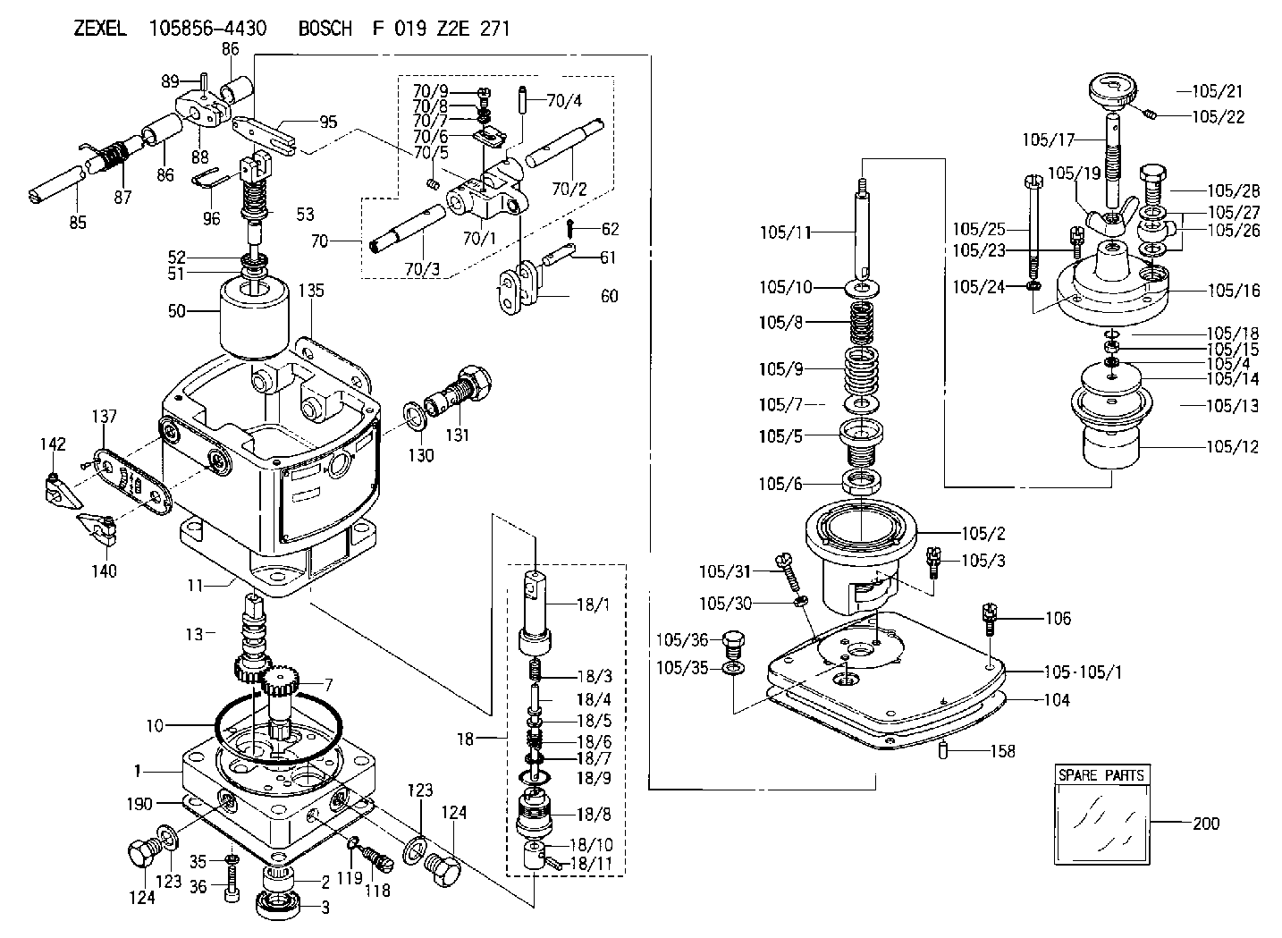
F 019 Z2E 271
f019z2e271
ZEXEL
105856-4430
1058564430
Rating:
Components :
| 0. | INJECTION-PUMP ASSEMBLY | 105856-4430 |
| 1. | _ | |
| 2. | FUEL INJECTION PUMP | |
| 3. | NUMBER PLATE | |
| 4. | _ | |
| 5. | CAPSULE | |
| 6. | ADJUSTING DEVICE | |
| 7. | NOZZLE AND HOLDER ASSY | |
| 8. | Nozzle and Holder | |
| 9. | Open Pre:MPa(Kqf/cm2) | |
| 10. | NOZZLE-HOLDER | |
| 11. | NOZZLE |
Scheme ###:
| 1. | [1] | 158502-0420 | BASE |
| 2. | [1] | 029811-8000 | BEARING PLATE |
| 3. | [1] | 158528-0900 | PACKING RING |
| 7. | [1] | 158131-0100 | GEAR SHAFT |
| 10. | [1] | 158028-0000 | O-RING |
| 11. | [1] | 158507-1820 | DIAPHRAGM HOUSING |
| 13. | [1] | 158621-0600 | SLIDING PIECE |
| 18. | [1] | 158699-0521 | COMPENSATOR ASSY |
| 18/1. | [1] | 158610-0901 | POWER PISTON |
| 18/3. | [1] | 158654-1000 | COILED SPRING |
| 18/4. | [1] | 158614-0300 | STOP PIN |
| 18/5. | [1] | 158612-0500 | PLAIN WASHER |
| 18/6. | [1] | 158654-1100 | COILED SPRING |
| 18/7. | [1] | 016110-1220 | LOCKING WASHER |
| 18/8. | [1] | 158612-0001 | BUSHING |
| 18/9. | [2] | 158528-1300 | O-RING |
| 18/10. | [1] | 158615-0400 | PUMP PLUNGER |
| 18/11. | [1] | 025620-1410 | SPRING PIN |
| 35. | [3] | 029330-6070 | GASKET |
| 36. | [3] | 010206-2520 | HEX-SOCKET-HEAD CAP SCREW |
| 50. | [1] | 158600-0720 | FLYWEIGHT ASSEMBLY |
| 51. | [1] | 158106-0100 | PLAIN WASHER |
| 52. | [1] | 029811-0000 | BEARING PLATE |
| 53. | [1] | 158620-1220 | PILOT VALVE |
| 60. | [2] | 158220-0000 | GUIDE LEVER |
| 61. | [2] | 158736-0200 | BEARING PIN |
| 62. | [4] | 025520-1510 | SPLIT PIN |
| 70. | [1] | 158730-0220 | TERMINAL ARM |
| 70/1. | [1] | 158230-0020 | TERMINAL ARM |
| 70/2. | [1] | 158315-0200 | TERMINAL SHAFT |
| 70/3. | [1] | 158315-0200 | TERMINAL SHAFT |
| 70/4. | [2] | 158736-0100 | TAPER PIN |
| 70/5. | [2] | 011006-0620 | SET OF NUTS |
| 70/6. | [1] | 158214-0020 | SPEED DROOP ADJUSTER |
| 70/7. | [1] | 014020-5120 | PLAIN WASHER |
| 70/8. | [1] | 029320-5030 | TAB WASHER |
| 70/9. | [1] | 010535-1220 | FLAT-HEAD SCREW |
| 85. | [1] | 158814-0900 | SPEED CONTROL SHAFT |
| 86. | [2] | 158823-0300 | BUSHING |
| 86. | [2] | 158823-0300 | BUSHING |
| 87. | [1] | 158322-0200 | COILED SPRING |
| 88. | [1] | 158710-0400 | STRAP |
| 89. | [1] | 029404-5010 | BEARING PIN |
| 95. | [1] | 158211-0100 | STRAP |
| 96. | [2] | 158653-0100 | WIRE |
| 104. | [1] | 158017-0900 | GASKET |
| 105. | [1] | 158963-5420 | PNEUMATIC CONTROLLER |
| 105/1. | [1] | 158562-4600 | COVER |
| 105/2. | [1] | 158910-0200 | CYLINDER |
| 105/3. | [3] | 029050-6090 | FLAT-HEAD SCREW |
| 105/4. | [1] | 014110-6440 | LOCKING WASHER |
| 105/5. | [1] | 158416-0000 | FLAT-HEAD SCREW |
| 105/6. | [1] | 158915-0700 | UNION NUT |
| 105/7. | [1] | 158918-0000 | PLAIN WASHER D30&10.8T1.00 |
| 105/8. | [1] | 158412-0300 | COILED SPRING K3.0 |
| 105/8A. | [1] | 158412-0100 | COILED SPRING K1.0 |
| 105/8B. | [1] | 158412-0400 | COILED SPRING K4.0 |
| 105/8C. | [1] | 158412-0500 | COILED SPRING K5.0 |
| 105/9. | [1] | 158912-0600 | COILED SPRING K5.1 |
| 105/9D. | [1] | 158912-1100 | COILED SPRING K4.8 |
| 105/9E. | [1] | 158912-1200 | COILED SPRING K5.4 |
| 105/10. | [1] | 158918-0000 | PLAIN WASHER D30&10.8T1.00 |
| 105/11. | [1] | 158413-0001 | STOP PIN |
| 105/12. | [1] | 158414-0000 | PUMP PLUNGER |
| 105/13. | [1] | 158414-0100 | DIAPHRAGM |
| 105/14. | [1] | 158414-0200 | PLATE |
| 105/15. | [1] | 013020-6040 | UNION NUT M6P1H5 |
| 105/16. | [1] | 158910-0300 | CAP |
| 105/17. | [1] | 158915-1000 | FLAT-HEAD SCREW |
| 105/18. | [1] | 029630-9050 | O-RING |
| 105/19. | [1] | 158567-1500 | WING NUT |
| 105/21. | [1] | 158904-2020 | ROUND NUT |
| 105/22. | [1] | 158916-0000 | SET OF NUTS |
| 105/23. | [2] | 029050-6220 | FLAT-HEAD SCREW |
| 105/24. | [2] | 029320-6010 | LOCKING WASHER |
| 105/25. | [2] | 158909-0200 | BLEEDER SCREW |
| 105/26. | [1] | 027114-1040 | INLET UNION |
| 105/27. | [2] | 029331-4120 | GASKET D18&14.2T1.5 |
| 105/28. | [1] | 027414-2640 | EYE BOLT |
| 105/30. | [1] | 013020-6040 | UNION NUT M6P1H5 |
| 105/31. | [1] | 158567-1200 | SET OF NUTS |
| 105/35. | [1] | 026512-1640 | GASKET D15.9&12.2T1 |
| 105/36. | [1] | 158066-0000 | BLEEDER SCREW |
| 106. | [4] | 029010-6350 | BLEEDER SCREW M6P1.0L22 |
| 118. | [1] | 158527-0200 | NEEDLE VALVE |
| 119. | [1] | 016500-0710 | O-RING |
| 123. | [2] | 026512-1640 | GASKET D15.9&12.2T1 |
| 123. | [2] | 026512-1640 | GASKET D15.9&12.2T1 |
| 124. | [2] | 029111-2070 | CAPSULE M12P1.5L10 |
| 124. | [2] | 029111-2070 | CAPSULE M12P1.5L10 |
| 130. | [1] | 029331-8040 | GASKET |
| 131. | [1] | 158660-0320 | CONTROL VALVE |
| 135. | [1] | 158515-0700 | INDICATOR PLATE |
| 137. | [1] | 158515-0800 | INDICATOR PLATE |
| 140. | [1] | 158820-0620 | POINTER |
| 142. | [1] | 158820-0620 | POINTER |
| 158. | [1] | 015040-0880 | BEARING PIN |
| 190. | [1] | 158017-1000 | GASKET |
| 200. | [1] | 158599-6920 | SPARE PART |
Include in #2:
105856-4430
as INJECTION-PUMP ASSEMBLY
Cross reference number
Zexel num
Bosch num
Firm num
Name
105856-4430
HYDRAULIC GOVERNOR
* K 35AA HYDRAULIC GOVERNOR Hydraulic RHD6 Others
* K 35AA HYDRAULIC GOVERNOR Hydraulic RHD6 Others
Information:
Illustration 4 g01456650
Position 253-7967 Bracket (6) behind the turbocharger in the location that is shown in Illustration 4.
Illustration 5 g01879437
(6) 253-7967 Bracket (15) 8T-4121 Hard Washer (17) 8T-4195 Bolt
Install bracket (6) by using four 8T-4195 Bolts (17) and four 8T-4121 Hard Washers (15). Refer to Illustration 5.
Illustration 6 g01879493
(7) 253-7973 Bracket (15) 8T-4121 Hard Washer (16) 8T-4133 Nuts (18) 8T-4196 Bolt
Install 253-7973 Bracket (7) by using two 8T-4196 Bolts (18), four 8T-4121 Hard Washers (15), and two 8T-4133 Nuts (16). Refer to Illustration 6.Note: The left side of bracket (7) will be bolted to the engine block while the right side of the bracket will be free.
Illustration 7 g01879515
(3) 108-8625 Exhaust Coupling
Install one end of 108-8625 Exhaust Coupling (3) and 6N-0009 Metal Seal Ring (1) (not shown) into the end of the turbocharger. Refer to Illustration 7.
Illustration 8 g01879516
(2) 7E-3870 Muffler Clamp (3) 108-8625 Exhaust Coupling (8) 277-4717 Exhaust Elbow (15) 8T-4121 Hard Washer (17) 8T-4195 Bolt
Install 277-4717 Exhaust Elbow (8) by inserting the exhaust elbow into the other end of 108-8625 Exhaust Coupling (3). Tighten the exhaust elbow to the engine block by using four 8T-4195 Bolts (17) and four 8T-4121 Hard Washers (15). Tighten the four bolts to a torque of 7.5 N m (66 lb in). Refer to Illustration 8.
Apply 4C-5597 Anti-Seize Compound to the treads of 7E-3870 Muffler Clamp (2) and place the muffler clamp on exhaust coupling (3). Leave the muffler clamp positioned loosely. Refer to Illustration 8.
Illustration 9 g01879521
(5) 253-4495 Clamp As (6) 253-7967 Bracket (7) 253-7973 Bracket (15) 8T-4121 Hard Washer (16) 8T-4133 Nuts (18) 8T-4196 Bolt
Install one 253-4495 Clamp Assembly (5) to 253-7967 Bracket (6). Use two 8T-4196 Bolts (18), four 8T-4121 Hard Washers (15), and two 8T-4133 Nuts (16) to tighten clamp assembly (5) to bracket (6). Refer to Illustration 9.
Install the other 253-4495 Clamp Assembly (5) to 253-7973 Bracket (7). Use two 8T-4196 Bolts (18), four 8T-4121 Hard Washers (15), and two 8T-4133 Nuts (16) to tighten clamp assembly (5) to bracket (7). Refer to Illustration 9.
Illustration 10 g01879798
(4) 253-4346 Diesel Particulate Filter Gp (5) 253-4495 Clamp As (8) 277-4717 Exhaust Elbow
Install 253-4346 Diesel Particulate Filter Gp (4) by placing the diesel particulate filter group onto clamp assemblies (5) and inserting the inlet tube over the exposed end of exhaust elbow (8). The weight of the diesel particulate filter group is approximately 60 kg (132 lb). Refer to Illustration 10.
Illustration 11 g01879814
(5) 253-4495 Clamp As (9) 277-4718 Clamp As (10) 3B-4508 Lockwasher (12) 5P-8245 Hard Washer (13) 6V-8336 Bolt (14) 6V-8149 Nut
Position 277-4718 Clamp Assembly (9) over clamp assembly (5).