Information hydraulic governor
BOSCH
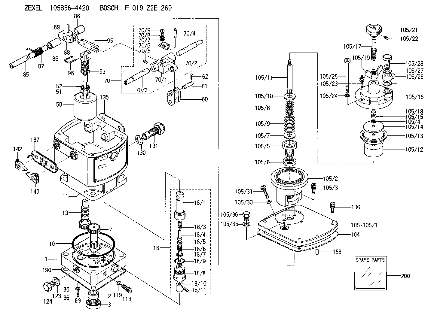
F 019 Z2E 269
f019z2e269
ZEXEL
105856-4420
1058564420
Rating:
Components :
| 0. | INJECTION-PUMP ASSEMBLY | 105856-4420 |
| 1. | _ | |
| 2. | FUEL INJECTION PUMP | |
| 3. | NUMBER PLATE | |
| 4. | _ | |
| 5. | CAPSULE | |
| 6. | ADJUSTING DEVICE | |
| 7. | NOZZLE AND HOLDER ASSY | |
| 8. | Nozzle and Holder | |
| 9. | Open Pre:MPa(Kqf/cm2) | |
| 10. | NOZZLE-HOLDER | |
| 11. | NOZZLE |
Scheme ###:
| 1. | [1] | 158502-0420 | BASE |
| 2. | [1] | 029811-8000 | BEARING PLATE |
| 3. | [1] | 158528-0900 | PACKING RING |
| 7. | [1] | 158131-0100 | GEAR SHAFT |
| 10. | [1] | 158028-0000 | O-RING |
| 11. | [1] | 158507-1820 | DIAPHRAGM HOUSING |
| 13. | [1] | 158621-0600 | SLIDING PIECE |
| 18. | [1] | 158699-0321 | COMPENSATOR ASSY |
| 18/1. | [1] | 158610-0901 | POWER PISTON |
| 18/3. | [1] | 158654-0400 | COILED SPRING |
| 18/4. | [1] | 158614-0300 | STOP PIN |
| 18/5. | [1] | 158612-0500 | PLAIN WASHER |
| 18/6. | [1] | 158654-0500 | COILED SPRING |
| 18/7. | [1] | 016110-1220 | LOCKING WASHER |
| 18/8. | [1] | 158612-0001 | BUSHING |
| 18/9. | [2] | 158528-1300 | O-RING |
| 18/10. | [1] | 158615-0300 | PUMP PLUNGER |
| 18/11. | [1] | 025620-1410 | SPRING PIN |
| 35. | [3] | 029330-6070 | GASKET |
| 36. | [3] | 010206-2520 | HEX-SOCKET-HEAD CAP SCREW |
| 50. | [1] | 158600-0720 | FLYWEIGHT ASSEMBLY |
| 51. | [1] | 158106-0100 | PLAIN WASHER |
| 52. | [1] | 029811-0000 | BEARING PLATE |
| 53. | [1] | 158620-1120 | PILOT VALVE |
| 60. | [2] | 158220-0000 | GUIDE LEVER |
| 61. | [2] | 158736-0200 | BEARING PIN |
| 62. | [4] | 025520-1510 | SPLIT PIN |
| 70. | [1] | 158730-0220 | TERMINAL ARM |
| 70/1. | [1] | 158230-0020 | TERMINAL ARM |
| 70/2. | [1] | 158315-0200 | TERMINAL SHAFT |
| 70/3. | [1] | 158315-0200 | TERMINAL SHAFT |
| 70/4. | [2] | 158736-0100 | TAPER PIN |
| 70/5. | [2] | 011006-0620 | SET OF NUTS |
| 70/6. | [1] | 158214-0020 | SPEED DROOP ADJUSTER |
| 70/7. | [1] | 014020-5120 | PLAIN WASHER |
| 70/8. | [1] | 029320-5030 | TAB WASHER |
| 70/9. | [1] | 010535-1220 | FLAT-HEAD SCREW |
| 85. | [1] | 158814-0900 | SPEED CONTROL SHAFT |
| 86. | [2] | 158823-0300 | BUSHING |
| 86. | [2] | 158823-0300 | BUSHING |
| 87. | [1] | 158322-0200 | COILED SPRING |
| 88. | [1] | 158710-0400 | STRAP |
| 89. | [1] | 029404-5010 | BEARING PIN |
| 95. | [1] | 158211-0100 | STRAP |
| 96. | [2] | 158653-0100 | WIRE |
| 104. | [1] | 158017-0900 | GASKET |
| 105. | [1] | 158962-7720 | PNEUMATIC CONTROLLER |
| 105/1. | [1] | 158562-4600 | COVER |
| 105/2. | [1] | 158910-0200 | CYLINDER |
| 105/3. | [3] | 029050-6090 | FLAT-HEAD SCREW |
| 105/4. | [1] | 014110-6440 | LOCKING WASHER |
| 105/5. | [1] | 158416-0000 | FLAT-HEAD SCREW |
| 105/6. | [1] | 158915-0700 | UNION NUT |
| 105/7. | [1] | 158918-0000 | PLAIN WASHER D30&10.8T1.00 |
| 105/8. | [1] | 158412-0300 | COILED SPRING K3.0 |
| 105/9. | [1] | 158912-0600 | COILED SPRING K5.1 |
| 105/10. | [1] | 158918-0000 | PLAIN WASHER D30&10.8T1.00 |
| 105/11. | [1] | 158413-0001 | STOP PIN |
| 105/12. | [1] | 158414-0000 | PUMP PLUNGER |
| 105/13. | [1] | 158414-0100 | DIAPHRAGM |
| 105/14. | [1] | 158414-0200 | PLATE |
| 105/15. | [1] | 013020-6040 | UNION NUT M6P1H5 |
| 105/16. | [1] | 158910-0300 | CAP |
| 105/17. | [1] | 158915-1000 | FLAT-HEAD SCREW |
| 105/18. | [1] | 029630-9050 | O-RING |
| 105/19. | [1] | 158567-1500 | WING NUT |
| 105/21. | [1] | 158904-2020 | ROUND NUT |
| 105/22. | [1] | 158916-0000 | SET OF NUTS |
| 105/23. | [2] | 029050-6220 | FLAT-HEAD SCREW |
| 105/24. | [2] | 029320-6010 | LOCKING WASHER |
| 105/25. | [2] | 158909-0200 | BLEEDER SCREW |
| 105/26. | [1] | 027114-1040 | INLET UNION |
| 105/27. | [2] | 029331-4120 | GASKET D18&14.2T1.5 |
| 105/28. | [1] | 027414-2640 | EYE BOLT |
| 105/30. | [1] | 013020-6040 | UNION NUT M6P1H5 |
| 105/31. | [1] | 158567-1200 | SET OF NUTS |
| 105/35. | [1] | 026512-1640 | GASKET D15.9&12.2T1 |
| 105/36. | [1] | 158066-0000 | BLEEDER SCREW |
| 106. | [4] | 029010-6350 | BLEEDER SCREW M6P1.0L22 |
| 118. | [1] | 158027-0100 | NEEDLE VALVE |
| 119. | [1] | 016500-0710 | O-RING |
| 123. | [2] | 026512-1640 | GASKET D15.9&12.2T1 |
| 124. | [2] | 029111-2070 | CAPSULE M12P1.5L10 |
| 130. | [1] | 029331-8040 | GASKET |
| 131. | [1] | 158660-0020 | CONTROL VALVE |
| 135. | [1] | 158515-0700 | INDICATOR PLATE |
| 137. | [1] | 158515-0800 | INDICATOR PLATE |
| 140. | [1] | 158820-0620 | POINTER |
| 142. | [1] | 158820-0620 | POINTER |
| 158. | [1] | 015040-0880 | BEARING PIN |
| 190. | [1] | 158017-1000 | GASKET |
| 200. | [1] | 158599-6920 | SPARE PART |
Include in #2:
105856-4420
as INJECTION-PUMP ASSEMBLY
Cross reference number
Zexel num
Bosch num
Firm num
Name
Information:
Table 1
Part Number Container Size Volume of Finished Coolant Produced
351-9431 3.8 L (1 US gal) 50.5 L (13.3 US gal)
351-9432 20 L (5.3 US gal) 267 L (70.5 US gal)
351-9433 208 L (55 US gal) 2773 L (733 US gal)
366-2753 (1) 1000 L (264 US gal) 13333 L (3523 US gal)
(1) NACD and LACD onlyMixing Cat ELI
The recommended water for mixing with Cat ELI concentrate is distilled or deionized water. Water must meet requirements of ASTM 1193, "Type IV Reagent Water Specification". If distilled or deionized water is not available, water should meet the “Caterpillar Minimum Acceptable Water Requirements” provided in this Special Publication.To ensure a proper concentration, the preferred method is to mix Cat ELI concentrate with water. Then, add the mixed coolant to the engine cooling system. Add the proper amounts of water and Cat ELI into a clean container and mix thoroughly by manual stirring or mechanical agitation.If the preferred method cannot be performed, a Cat ELI mixture can be made by adding Cat ELI concentrate directly into engine cooling system. Add good quality water until the dilution level is approximately 7.5%. Adequate mixing is attained by operating the engine for at least 30 minutes.Appropriate mixing rates for available ELI container sizes are provided in Table 1.After the addition of water and proper mixing, the concentration of Cat ELI can be determined using the 360-0774 Digital Brix Refractometer.Changing to Cat ELI
For cooling systems previously running Cat ELC or an extended life coolant that meets Cat EC-1 requirements, drain the cooling system and flush with water. Then refill the cooling system with a mixture of 7.5% Cat ELI in water that meets the “Caterpillar Minimum Acceptable Water Requirements”.For cooling systems previously running a conventional heavy-duty coolant or a water/SCA mixture, follow the steps listed in this Special Publication, "Changing to Cat ELC". Then refill the cooling system with a mixture of 7.5% Cat ELI in water that meets the “Caterpillar Minimum Acceptable Water Requirements”.Cat ELI Maintenance
Maintenance of Cat ELI is similar to Cat ELC. A coolant sample should be submitted for S O S Level 2 Coolant Analysis after the first 500 hours of operation and then annually thereafter.Cat ELC Extender should be added at the midpoint of service life (typically 6,000 hours), or as recommended by S O S Coolant Analysis results.Analysis and interpretation of Cat ELI S O S results is similar to the analysis and interpretation of Cat ELC. There will be no glycol and glycol oxidation products, which do not apply to Cat ELI.The concentration of a sample of in-use Cat ELI taken from the cooling system can also be determined using the 360-0774 Digital Brix Refractometer.Note: Clean water is the only flushing agent that is required when Cat ELI is drained from a properly maintained cooling system.Mixing Cat ELI and Cat ELC
Since Cat ELI and Cat ELC are based on the same corrosion inhibitor technology, Cat ELI can be mixed with Cat