Information hydraulic governor
BOSCH
F 019 Z2E 220
f019z2e220
ZEXEL
105856-3270
1058563270
Rating:
Components :
| 0. | INJECTION-PUMP ASSEMBLY | 105856-3270 |
| 1. | _ | |
| 2. | FUEL INJECTION PUMP | |
| 3. | NUMBER PLATE | |
| 4. | _ | |
| 5. | CAPSULE | |
| 6. | ADJUSTING DEVICE | |
| 7. | NOZZLE AND HOLDER ASSY | |
| 8. | Nozzle and Holder | |
| 9. | Open Pre:MPa(Kqf/cm2) | |
| 10. | NOZZLE-HOLDER | |
| 11. | NOZZLE |
Scheme ###:
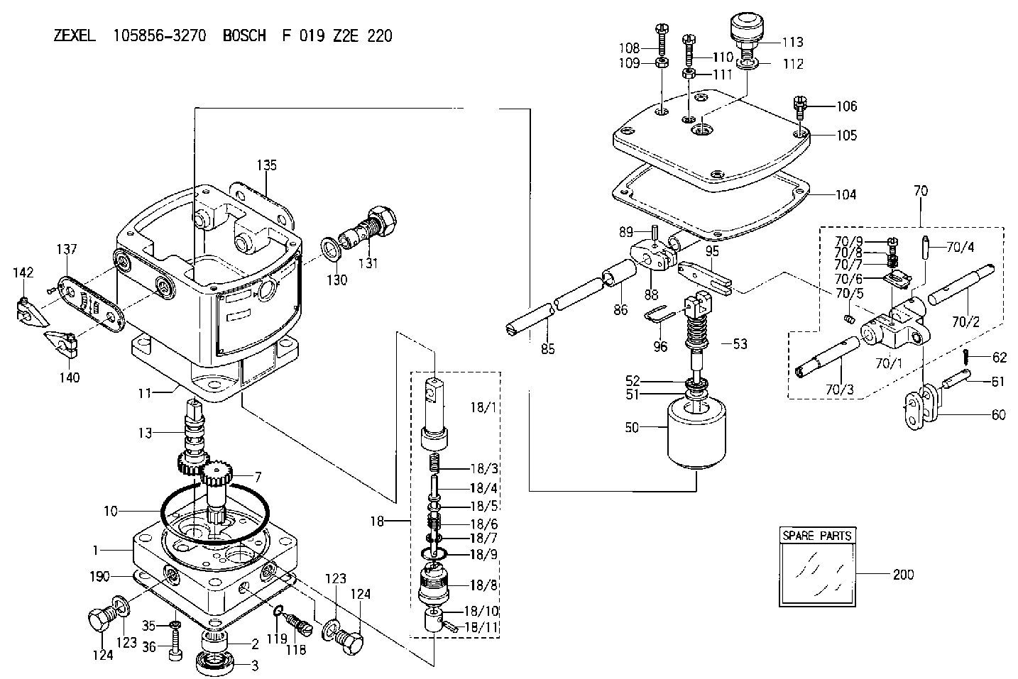
| 1. | [1] | 158502-0420 | BASE |
| 2. | [1] | 029811-8000 | BEARING PLATE |
| 3. | [1] | 158528-0900 | PACKING RING |
| 7. | [1] | 158131-0100 | GEAR SHAFT |
| 10. | [1] | 158028-0000 | O-RING |
| 11. | [1] | 158507-1820 | DIAPHRAGM HOUSING |
| 13. | [1] | 158621-0500 | SLEEVE |
| 18. | [1] | 158699-0321 | COMPENSATOR ASSY |
| 18/1. | [1] | 158610-0901 | POWER PISTON |
| 18/3. | [1] | 158654-0400 | COILED SPRING |
| 18/4. | [1] | 158614-0300 | STOP PIN |
| 18/5. | [1] | 158612-0500 | PLAIN WASHER |
| 18/6. | [1] | 158654-0500 | COILED SPRING |
| 18/7. | [1] | 016110-1220 | LOCKING WASHER |
| 18/8. | [1] | 158612-0001 | BUSHING |
| 18/9. | [2] | 158528-1300 | O-RING |
| 18/10. | [1] | 158615-0300 | PUMP PLUNGER |
| 18/11. | [1] | 025620-1410 | SPRING PIN |
| 35. | [3] | 029330-6070 | GASKET |
| 36. | [3] | 010206-2520 | HEX-SOCKET-HEAD CAP SCREW |
| 50. | [1] | 158600-0720 | FLYWEIGHT ASSEMBLY |
| 51. | [1] | 158106-0100 | PLAIN WASHER |
| 52. | [1] | 029811-0000 | BEARING PLATE |
| 53. | [1] | 158620-1320 | PILOT VALVE |
| 60. | [2] | 158220-0000 | GUIDE LEVER |
| 61. | [2] | 158736-0200 | BEARING PIN |
| 62. | [4] | 025520-1510 | SPLIT PIN |
| 70. | [1] | 158730-0220 | TERMINAL ARM |
| 70/1. | [1] | 158230-0020 | TERMINAL ARM |
| 70/2. | [1] | 158315-0200 | TERMINAL SHAFT |
| 70/3. | [1] | 158315-0200 | TERMINAL SHAFT |
| 70/4. | [2] | 158736-0100 | TAPER PIN |
| 70/5. | [2] | 011006-0620 | SET OF NUTS |
| 70/6. | [1] | 158214-0020 | SPEED DROOP ADJUSTER |
| 70/7. | [1] | 014020-5120 | PLAIN WASHER |
| 70/8. | [1] | 029320-5030 | TAB WASHER |
| 70/9. | [1] | 010535-1220 | FLAT-HEAD SCREW |
| 85. | [1] | 158814-0900 | SPEED CONTROL SHAFT |
| 86. | [2] | 158823-0300 | BUSHING |
| 88. | [1] | 158710-0400 | STRAP |
| 89. | [1] | 029404-5010 | BEARING PIN |
| 95. | [1] | 158211-0100 | STRAP |
| 96. | [2] | 158653-0100 | WIRE |
| 104. | [1] | 158017-0900 | GASKET |
| 105. | [1] | 158062-0100 | COVER |
| 106. | [4] | 029010-6350 | BLEEDER SCREW M6P1.0L22 |
| 108. | [1] | 158567-1200 | SET OF NUTS |
| 109. | [1] | 013020-6040 | UNION NUT M6P1H5 |
| 110. | [1] | 158567-1200 | SET OF NUTS |
| 111. | [1] | 013020-6040 | UNION NUT M6P1H5 |
| 112. | [1] | 026512-1640 | GASKET D15.9&12.2T1 |
| 113. | [1] | 155406-0220 | AIR FILTER |
| 118. | [1] | 158027-0100 | NEEDLE VALVE |
| 119. | [1] | 016500-0710 | O-RING |
| 123. | [2] | 026512-1640 | GASKET D15.9&12.2T1 |
| 123. | [2] | 026512-1640 | GASKET D15.9&12.2T1 |
| 124. | [2] | 029111-2070 | CAPSULE M12P1.5L10 |
| 124. | [2] | 029111-2070 | CAPSULE M12P1.5L10 |
| 130. | [1] | 029331-8040 | GASKET |
| 131. | [1] | 158660-0020 | CONTROL VALVE |
| 135. | [1] | 158515-0700 | INDICATOR PLATE |
| 137. | [1] | 158515-0800 | INDICATOR PLATE |
| 140. | [1] | 158820-0620 | POINTER |
| 142. | [1] | 158820-0620 | POINTER |
| 190. | [1] | 158017-1000 | GASKET |
| 200. | [1] | 158599-6720 | SPARE PART |
Include in #2:
105856-3270
as INJECTION-PUMP ASSEMBLY
Cross reference number
Zexel num
Bosch num
Firm num
Name
Information:
2. Disconnect air compressor line (2) and fuel ratio control line (3) from the aftercooler housing.3. Remove four bolts (1), nuts and cover that connect the inlet pipe to the aftercooler housing. 4. Put a mark on the turbocharger compressor housing in alignment with a mark on the turbocharger cartridge housing. Loosen the bolts for the turbocharger compressor housing. Turn the housing so air inlet pipe (4) is away from the aftercooler housing.5. Remove bolts (5) that hold the aftercooler housing to the cylinder head.6. Fasten a hoist to the aftercooler housing and remove the aftercooler housing from the engine. Weight is 95 lb. (43 kg).Install Aftercooler Housing
1. Install new O-ring seals on the aftercooler water inlet and outlet pipes. 2. Fasten a hoist to aftercooler housing (1) and put the aftercooler housing in position on the water pipes and cylinder head.3. Put 9S3263 Thread Lock on the threads of the bolts and install the bolts that hold the aftercooler housing to the cylinder head. 4. Turn the turbocharger compressor housing carefully so the mark on the housing is in alignment with the mark on the turbocharger cartridge housing. Tighten bolts (2) for the compressor housing to 105 5 lb.in. (11.9 0.6 N m).
Do not cause damage to the O-ring seal between the turbocharger compressor housing and the cartridge housing.
5. Install the four bolts and nuts that connect the air inlet pipe to the aftercooler housing.6. Connect the air compressor line and fuel ratio control line.7. Fill engine with coolant.end by:a) install fuel filter base