Information hydraulic governor
BOSCH
F 019 Z2E 219
f019z2e219
ZEXEL
105856-3260
1058563260
Rating:
Components :
| 0. | INJECTION-PUMP ASSEMBLY | 105856-3260 |
| 1. | _ | |
| 2. | FUEL INJECTION PUMP | |
| 3. | NUMBER PLATE | |
| 4. | _ | |
| 5. | CAPSULE | |
| 6. | ADJUSTING DEVICE | |
| 7. | NOZZLE AND HOLDER ASSY | |
| 8. | Nozzle and Holder | |
| 9. | Open Pre:MPa(Kqf/cm2) | |
| 10. | NOZZLE-HOLDER | |
| 11. | NOZZLE |
Scheme ###:
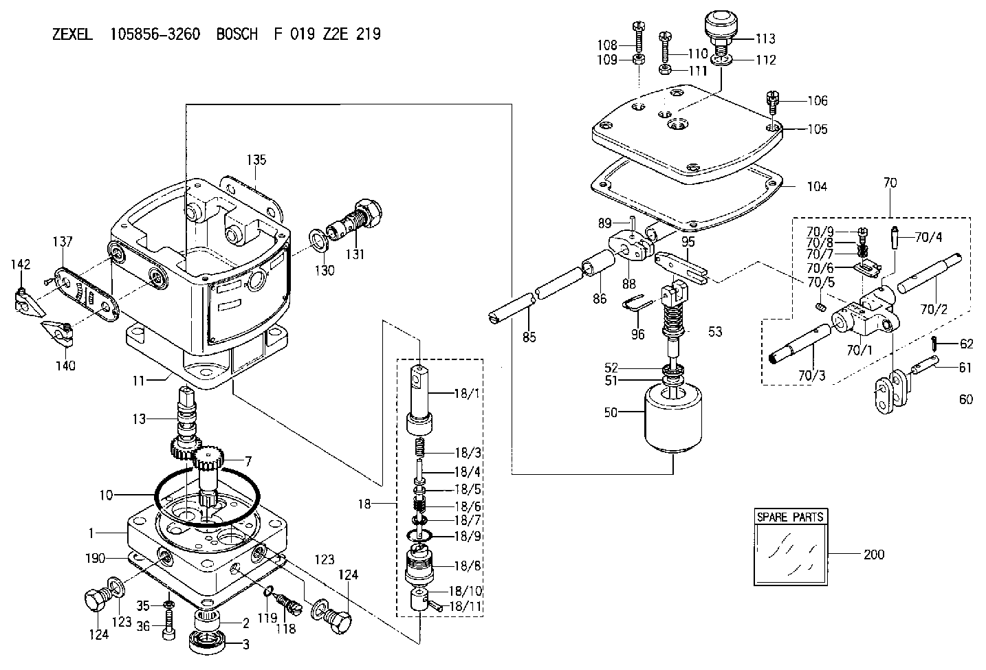
| 1. | [1] | 158502-0420 | BASE |
| 2. | [1] | 029811-8000 | BEARING PLATE |
| 3. | [1] | 158528-0900 | PACKING RING |
| 7. | [1] | 158131-0100 | GEAR SHAFT |
| 10. | [1] | 158028-0000 | O-RING |
| 11. | [1] | 158507-1820 | DIAPHRAGM HOUSING |
| 13. | [1] | 158621-0500 | SLEEVE |
| 18. | [1] | 158699-0321 | COMPENSATOR ASSY |
| 18/1. | [1] | 158610-0901 | POWER PISTON |
| 18/3. | [1] | 158654-0400 | COILED SPRING |
| 18/4. | [1] | 158614-0300 | STOP PIN |
| 18/5. | [1] | 158612-0500 | PLAIN WASHER |
| 18/6. | [1] | 158654-0500 | COILED SPRING |
| 18/7. | [1] | 016110-1220 | LOCKING WASHER |
| 18/8. | [1] | 158612-0001 | BUSHING |
| 18/9. | [2] | 158528-1300 | O-RING |
| 18/10. | [1] | 158615-0300 | PUMP PLUNGER |
| 18/11. | [1] | 025620-1410 | SPRING PIN |
| 35. | [3] | 029330-6070 | GASKET |
| 36. | [3] | 010206-2520 | HEX-SOCKET-HEAD CAP SCREW |
| 50. | [1] | 158600-0720 | FLYWEIGHT ASSEMBLY |
| 51. | [1] | 158106-0100 | PLAIN WASHER |
| 52. | [1] | 029811-0000 | BEARING PLATE |
| 53. | [1] | 158620-1120 | PILOT VALVE |
| 60. | [2] | 158220-0000 | GUIDE LEVER |
| 61. | [2] | 158736-0200 | BEARING PIN |
| 62. | [4] | 025520-1510 | SPLIT PIN |
| 70. | [1] | 158730-0220 | TERMINAL ARM |
| 70/1. | [1] | 158230-0020 | TERMINAL ARM |
| 70/2. | [1] | 158315-0200 | TERMINAL SHAFT |
| 70/3. | [1] | 158315-0200 | TERMINAL SHAFT |
| 70/4. | [2] | 158736-0100 | TAPER PIN |
| 70/5. | [2] | 011006-0620 | SET OF NUTS |
| 70/6. | [1] | 158214-0020 | SPEED DROOP ADJUSTER |
| 70/7. | [1] | 014020-5120 | PLAIN WASHER |
| 70/8. | [1] | 029320-5030 | TAB WASHER |
| 70/9. | [1] | 010535-1220 | FLAT-HEAD SCREW |
| 85. | [1] | 158814-0900 | SPEED CONTROL SHAFT |
| 86. | [2] | 158823-0300 | BUSHING |
| 88. | [1] | 158710-0400 | STRAP |
| 89. | [1] | 029404-5010 | BEARING PIN |
| 95. | [1] | 158211-0100 | STRAP |
| 96. | [2] | 158653-0100 | WIRE |
| 104. | [1] | 158017-0900 | GASKET |
| 105. | [1] | 158062-0100 | COVER |
| 106. | [4] | 029010-6350 | BLEEDER SCREW M6P1.0L22 |
| 108. | [1] | 158567-1200 | SET OF NUTS |
| 109. | [1] | 013020-6040 | UNION NUT M6P1H5 |
| 110. | [1] | 158567-1200 | SET OF NUTS |
| 111. | [1] | 013020-6040 | UNION NUT M6P1H5 |
| 112. | [1] | 026512-1640 | GASKET D15.9&12.2T1 |
| 113. | [1] | 155406-0220 | AIR FILTER |
| 118. | [1] | 158027-0100 | NEEDLE VALVE |
| 119. | [1] | 016500-0710 | O-RING |
| 123. | [2] | 026512-1640 | GASKET D15.9&12.2T1 |
| 123. | [2] | 026512-1640 | GASKET D15.9&12.2T1 |
| 124. | [2] | 029111-2070 | CAPSULE M12P1.5L10 |
| 124. | [2] | 029111-2070 | CAPSULE M12P1.5L10 |
| 130. | [1] | 029331-8040 | GASKET |
| 131. | [1] | 158660-0020 | CONTROL VALVE |
| 135. | [1] | 158515-0700 | INDICATOR PLATE |
| 137. | [1] | 158515-0800 | INDICATOR PLATE |
| 140. | [1] | 158820-0620 | POINTER |
| 142. | [1] | 158820-0620 | POINTER |
| 190. | [1] | 158017-1000 | GASKET |
| 200. | [1] | 158599-6720 | SPARE PART |
Include in #2:
105856-3260
as INJECTION-PUMP ASSEMBLY
Cross reference number
Zexel num
Bosch num
Firm num
Name
105856-3260
HYDRAULIC GOVERNOR
K 35AA HYDRAULIC GOVERNOR Hydraulic RHD6 Others
K 35AA HYDRAULIC GOVERNOR Hydraulic RHD6 Others
Information:
start by:a) separation of governor from fuel injection pump housing 1. Remove the protection caps and felt washers (1) from pumps.2. Use wrench (A) to remove bushings (2) that hold the fuel injection pumps into the housing. Remove seals (3).3. Use extractor (B) to remove the pumps from the pump housing. Put identification on the injection pumps as to their location in the pump housing.4. Remove bonnet (4), ring (5), spring (6) and check valve (7) from barrel (8).5. Remove plunger assembly (11), washer (10) and spring (9) from the barrel.
Be careful not to cause damage to plunger assemblies. Keep the same cylinder pump and plunger together, the plunger from one pump can not be installed in another group.
6. Remove rack (12) from the housing. 7. Remove spacers (13) and lifters (14) from the housing. Keep the spacers and lifters together with identification as to their location in the pump housing. 8. Remove two bolts (16), lock and two sleeves from the gear assembly.9. Remove gear assembly (15) from the camshaft. 10. Remove two bolts, plate (17) and the spacer that hold the camshaft in position in the pump housing. 11. Remove the camshaft from the pump housing. 12. Use tool group (C) to remove the camshaft bearings from the pump housing.13. Remove the bearings for the fuel rack from the pump housing.Assemble Fuel Injection Pump Housing
1. Use tooling (C) to install the camshaft bearings in the fuel injection pump housing. Install the camshaft bearing joints 15° from the vertical centerline of the bores. Install the front and rear camshaft bearings even with the fuel injection pump housing. Install the center camshaft bearing a distance of 4.81 .02 in. (122.2 0.5 mm) from the rear face of the fuel injection pump housing. 2. Use tooling (F) to install the bearing with a tab for the groove in the rack.3. Use tooling (E) to install the rear bearing for the rack. Install the bearing to a depth of .282 .005 in. (7.16 0.13 mm). The small holes in the rear bearing must be installed parallel to the vertical centerline of the pump. 4. Put clean engine oil on the camshaft. Install the camshaft in the pump housing. 5. Install the spacer, plate (1) and two bolts that hold the camshaft in place in the pump housing. 6. Put gear assembly (2) in position on the end of the camshaft. Be sure rod (3) is in the groove of the camshaft. 7. Install sleeves (4), lock and two bolts on the gear assembly. 8. Install spacers (5) with their respective lifters (6) in the pump housing. If new lifters and/or pumps are to be installed, make adjustment of the fuel pump timing dimension. See SETTING THE INJECTION PUMP TIMING DIMENSION: OFF ENGINE TESTING AND ADJUSTING. 9. Install rack (7) in the pump housing.10. Assemble the fuel injection pumps as follows: a) Put clean fuel on all parts.b) Install the spring, washers and plunger in the