Information hydraulic governor
BOSCH
F 019 Z2E 218
f019z2e218
ZEXEL
105856-3251
1058563251
Rating:
Components :
| 0. | INJECTION-PUMP ASSEMBLY | 105856-3251 |
| 1. | _ | |
| 2. | FUEL INJECTION PUMP | |
| 3. | NUMBER PLATE | |
| 4. | _ | |
| 5. | CAPSULE | |
| 6. | ADJUSTING DEVICE | |
| 7. | NOZZLE AND HOLDER ASSY | |
| 8. | Nozzle and Holder | |
| 9. | Open Pre:MPa(Kqf/cm2) | |
| 10. | NOZZLE-HOLDER | |
| 11. | NOZZLE |
Scheme ###:
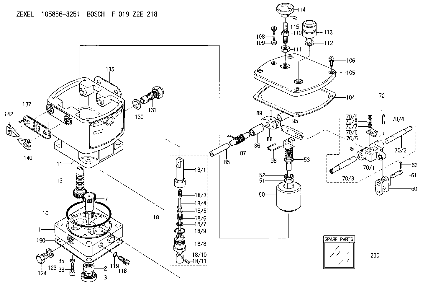
| 1. | [1] | 158502-0420 | BASE |
| 2. | [1] | 029811-8000 | BEARING PLATE |
| 3. | [1] | 158528-0900 | PACKING RING |
| 7. | [1] | 158131-0100 | GEAR SHAFT |
| 10. | [1] | 158028-0000 | O-RING |
| 11. | [1] | 158507-1820 | DIAPHRAGM HOUSING |
| 13. | [1] | 158621-0500 | SLEEVE |
| 18. | [1] | 158699-0321 | COMPENSATOR ASSY |
| 18/1. | [1] | 158610-0901 | POWER PISTON |
| 18/3. | [1] | 158654-0400 | COILED SPRING |
| 18/4. | [1] | 158614-0300 | STOP PIN |
| 18/5. | [1] | 158612-0500 | PLAIN WASHER |
| 18/6. | [1] | 158654-0500 | COILED SPRING |
| 18/7. | [1] | 016110-1220 | LOCKING WASHER |
| 18/8. | [1] | 158612-0001 | BUSHING |
| 18/9. | [2] | 158528-1300 | O-RING |
| 18/10. | [1] | 158615-0300 | PUMP PLUNGER |
| 18/11. | [1] | 025620-1410 | SPRING PIN |
| 35. | [3] | 029330-6070 | GASKET |
| 36. | [3] | 010206-2520 | HEX-SOCKET-HEAD CAP SCREW |
| 50. | [1] | 158600-1120 | FLYWEIGHT ASSEMBLY |
| 51. | [1] | 158106-0100 | PLAIN WASHER |
| 52. | [1] | 029811-0000 | BEARING PLATE |
| 53. | [1] | 158620-1120 | PILOT VALVE |
| 60. | [2] | 158220-0000 | GUIDE LEVER |
| 61. | [2] | 158736-0200 | BEARING PIN |
| 62. | [4] | 025520-1510 | SPLIT PIN |
| 70. | [1] | 158730-0220 | TERMINAL ARM |
| 70/1. | [1] | 158230-0020 | TERMINAL ARM |
| 70/2. | [1] | 158315-0200 | TERMINAL SHAFT |
| 70/3. | [1] | 158315-0200 | TERMINAL SHAFT |
| 70/4. | [2] | 158736-0100 | TAPER PIN |
| 70/5. | [2] | 011006-0620 | SET OF NUTS |
| 70/6. | [1] | 158214-0020 | SPEED DROOP ADJUSTER |
| 70/7. | [1] | 014020-5120 | PLAIN WASHER |
| 70/8. | [1] | 029320-5030 | TAB WASHER |
| 70/9. | [1] | 010535-1220 | FLAT-HEAD SCREW |
| 85. | [1] | 158814-0900 | SPEED CONTROL SHAFT |
| 86. | [2] | 158823-0300 | BUSHING |
| 87. | [1] | 158322-0200 | COILED SPRING |
| 88. | [1] | 158710-0400 | STRAP |
| 89. | [1] | 029404-5010 | BEARING PIN |
| 95. | [1] | 158211-0100 | STRAP |
| 96. | [2] | 158653-0100 | WIRE |
| 104. | [1] | 158017-0900 | GASKET |
| 105. | [1] | 158562-8720 | COVER |
| 106. | [4] | 029010-6350 | BLEEDER SCREW M6P1.0L22 |
| 108. | [1] | 158567-1200 | SET OF NUTS |
| 109. | [1] | 013020-6040 | UNION NUT M6P1H5 |
| 110. | [1] | 158567-1400 | SET OF NUTS |
| 111. | [1] | 158567-1300 | UNION NUT |
| 112. | [1] | 026512-1640 | GASKET D15.9&12.2T1 |
| 113. | [1] | 378050-6120 | AIR FILTER |
| 114. | [1] | 158904-1920 | ROUND NUT |
| 115. | [1] | 011206-1020 | SET OF NUTS |
| 118. | [1] | 158027-0100 | NEEDLE VALVE |
| 119. | [1] | 016500-0710 | O-RING |
| 123. | [2] | 026512-1640 | GASKET D15.9&12.2T1 |
| 124. | [2] | 029111-2070 | CAPSULE M12P1.5L10 |
| 130. | [1] | 029331-8040 | GASKET |
| 131. | [1] | 158660-0020 | CONTROL VALVE |
| 135. | [1] | 158515-0700 | INDICATOR PLATE |
| 137. | [1] | 158515-0800 | INDICATOR PLATE |
| 140. | [2] | 158820-0620 | POINTER |
| 142. | [2] | 158820-0620 | POINTER |
| 190. | [1] | 158017-1000 | GASKET |
| 200. | [1] | 158599-6720 | SPARE PART |
Include in #2:
105856-3251
as INJECTION-PUMP ASSEMBLY
Cross reference number
Zexel num
Bosch num
Firm num
Name
Information:
start by:a) separation of governor from fuel injection pump housing 1. Remove the ring (3) and pin (1) that hold seat (2). 2. Remove seat (2), bolt (4), washers (6) and spring (5).3. Remove the sleeve and bearing assembly from the cylinder and weight assemblies. 4. Remove ring (7) from sleeve (8).5. Remove bearing (9) and washers (10) from sleeve (8). 6. Remove valve (12) from piston (11). 7. Remove ring (15) that holds the weight assembly to cylinder (16).8. Remove weight assembly (13) from the cylinder.9. Remove piston (11) and sleeve (14) from the cylinder. Remove the O-ring seal from sleeve (14). 10. Remove speed limiter plug (20), spring and plunger from the governor housing (19).11. Remove torque spring assembly (17). 12. Remove bolt (21) and lock that hold lever (22) to shaft (18).13. Remove lever (22) and shaft from the housing.14. Remove the seal from housing (19).15. Remove the bearings and plug from the housing with tooling (A). 16. Remove two bolts (23), lock, lever arm (26) and shaft (25) from idle screw housing (24).17. Remove the two seals, bearings and plug from housing (24) with tooling (A).Assemble Governor
1. Use tooling (A) to install inner seal (3) in idle screw housing (2). Install seal (3) so the lip of the seal is toward bearing (4). Put clean engine oil on the lips of the seals.2. Use tooling (A) to install bearing (1) and the outer seal. Install the outer seal with the lip of the seal toward the outside. Install bearing (4). 3. Install bearing (6) in governor housing (8) to dimension (Y) or .897 .010 in. (22.97 0.25 mm) with tooling (A). Install bearing (5) in the governor housing to dimension (X) or 2.385 .005 in. (60.58 0.13 mm) from bearing (6). Install plug (7) in the governor housing. 4. Use tooling (A) to install the seal in governor housing (8). Install the seal with the lip of the seal toward the inside.5. Install torque spring assembly (9) on the governor housing. Install the lock and bolts that hold it. See RACK SETTING INFORMATION for the correct adjustment of the torque spring assembly. 6. Put lever assembly (11) in position in the governor housing. Install shaft (10) in the housing through the lever. Install the lock and bolt that hold the lever to the shaft. 7. Install speed limiter plunger (14), spring (13) and plug (12) in the governor housing. 8. Install O-ring seal (17) on sleeve (18).9. Install piston (16) and the sleeve in cylinder (15). 10. Put weight assembly (19) on cylinder (15). Install the ring that holds the weight assembly on the cylinder. 11. Install valve (21) in piston (16).12. Install bearing and washers (22) on sleeve (20). Install the ring that holds the washers and bearing on the sleeve.13. Install the sleeve assembly on valve (21). 14. Install bolt (23) in seat (24). Install the washers and spring in the seat.15. Put the seat in position on
1. Use tooling (A) to install inner seal (3) in idle screw housing (2). Install seal (3) so the lip of the seal is toward bearing (4). Put clean engine oil on the lips of the seals.2. Use tooling (A) to install bearing (1) and the outer seal. Install the outer seal with the lip of the seal toward the outside. Install bearing (4). 3. Install bearing (6) in governor housing (8) to dimension (Y) or .897 .010 in. (22.97 0.25 mm) with tooling (A). Install bearing (5) in the governor housing to dimension (X) or 2.385 .005 in. (60.58 0.13 mm) from bearing (6). Install plug (7) in the governor housing. 4. Use tooling (A) to install the seal in governor housing (8). Install the seal with the lip of the seal toward the inside.5. Install torque spring assembly (9) on the governor housing. Install the lock and bolts that hold it. See RACK SETTING INFORMATION for the correct adjustment of the torque spring assembly. 6. Put lever assembly (11) in position in the governor housing. Install shaft (10) in the housing through the lever. Install the lock and bolt that hold the lever to the shaft. 7. Install speed limiter plunger (14), spring (13) and plug (12) in the governor housing. 8. Install O-ring seal (17) on sleeve (18).9. Install piston (16) and the sleeve in cylinder (15). 10. Put weight assembly (19) on cylinder (15). Install the ring that holds the weight assembly on the cylinder. 11. Install valve (21) in piston (16).12. Install bearing and washers (22) on sleeve (20). Install the ring that holds the washers and bearing on the sleeve.13. Install the sleeve assembly on valve (21). 14. Install bolt (23) in seat (24). Install the washers and spring in the seat.15. Put the seat in position on